Crown Audio Advanced Features and Options continued, MA-5002VZ Power Amplifier, page

Models: MA-5002VZ

1 28
Download 28 pages 33.66 Kb
Page 16
Image 16
5 Advanced Features

MA-5002VZPower Amplifier

5 Advanced Features

and Options (continued)

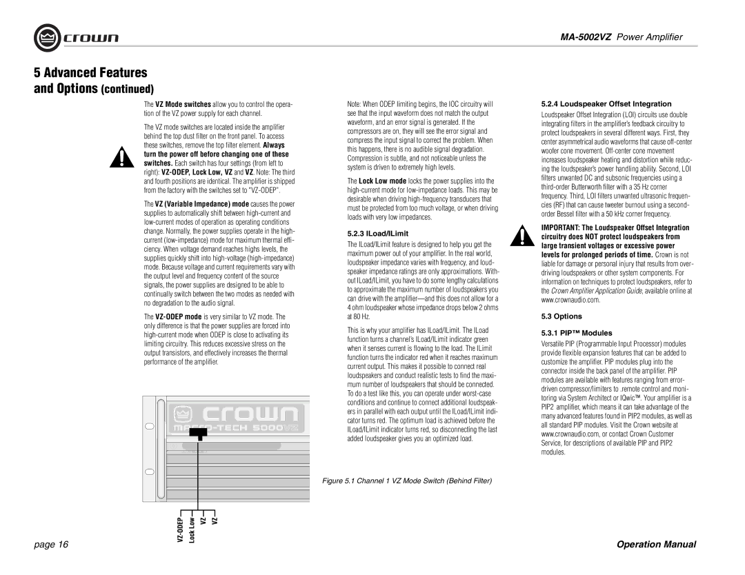
The VZ Mode switches allow you to control the opera-

Note: When ODEP limiting begins, the IOC circuitry will

tion of the VZ power supply for each channel.

see that the input waveform does not match the output

The VZ mode switches are located inside the amplifier

waveform, and an error signal is generated. If the

compressors are on, they will see the error signal and

behind the top dust filter on the front panel. To access

compress the input signal to correct the problem. When

these switches, remove the top filter element. Always

this happens, there is no audible signal degradation.

turn the power off before changing one of these

Compression is subtle, and not noticeable unless the

switches. Each switch has four settings (from left to

system is driven to extremely high levels.

right): VZ-ODEP, Lock Low, VZ and VZ. Note: The third

The Lock Low mode locks the power supplies into the

and fourth positions are identical. The amplifier is shipped

from the factory with the switches set to "VZ-ODEP”.

high-current mode for low-impedance loads. This may be

The VZ (Variable Impedance) mode causes the power

desirable when driving high-frequency transducers that

must be protected from too much voltage, or when driving

supplies to automatically shift between high-current and

loads with very low impedances.

low-current modes of operation as operating conditions


change. Normally, the power supplies operate in the high-

5.2.3 ILoad/ILimit

current (low-impedance) mode for maximum thermal effi-

The ILoad/ILimit feature is designed to help you get the

ciency. When voltage demand reaches highs levels, the

maximum power out of your amplifier. In the real world,

supplies quickly shift into high-voltage (high-impedance)

loudspeaker impedance varies with frequency, and loud-

mode. Because voltage and current requirements vary with

speaker impedance ratings are only approximations. With-

the output level and frequency content of the source

out ILoad/ILimit, you have to do some lengthy calculations

signals, the power supplies are designed to be able to

to approximate the maximum number of loudspeakers you

continually switch between the two modes as needed with

can drive with the amplifier—and this does not allow for a

no degradation to the audio signal.

4 ohm loudspeaker whose impedance drops below 2 ohms


The VZ-ODEP mode is very similar to VZ mode. The

at 80 Hz.

only difference is that the power supplies are forced into

This is why your amplifier has ILoad/ILimit. The ILoad

high-current mode when ODEP is close to activating its

function turns a channel’s ILoad/ILimit indicator green

limiting circuitry. This reduces excessive stress on the

when it senses current is flowing to the load. The ILimit

output transistors, and effectively increases the thermal

function turns the indicator red when it reaches maximum

performance of the amplifier.

current output. This makes it possible to connect real


loudspeakers and conduct realistic tests to find the maxi-


mum number of loudspeakers that should be connected.


To do a test like this, you can operate under worst-case


conditions and continue to connect additional loudspeak-


ers in parallel with each output until the ILoad/ILimit indi-


cator turns red. The optimum load is achieved before the


ILoad/ILimit indicator turns red, so disconnecting the last


added loudspeaker gives you an optimized load.


Figure 5.1 Channel 1 VZ Mode Switch (Behind Filter)


5.2.4 Loudspeaker Offset Integration

Loudspeaker Offset Integration (LOI) circuits use double integrating filters in the amplifier’s feedback circuitry to protect loudspeakers in several different ways. First, they center asymmetrical audio waveforms that cause off-center woofer cone movement. Off-center cone movement increases loudspeaker heating and distortion while reduc- ing the loudspeaker’s power handling ability. Second, LOI filters unwanted DC and subsonic frequencies using a third-order Butterworth filter with a 35 Hz corner frequency. Third, LOI filters unwanted ultrasonic frequen- cies (RF) that can cause tweeter burnout using a second- order Bessel filter with a 50 kHz corner frequency.

IMPORTANT: The Loudspeaker Offset Integration circuitry does NOT protect loudspeakers from large transient voltages or excessive power levels for prolonged periods of time. Crown is not liable for damage or personal injury that results from over- driving loudspeakers or other system components. For information on techniques to protect loudspeakers, refer to the Crown Amplifier Application Guide, available online at www.crownaudio.com.

5.3 Options

5.3.1 PIP™ Modules

Versatile PIP (Programmable Input Processor) modules provide flexible expansion features that can be added to customize the amplifier. PIP modules plug into the connector inside the back panel of the amplifier. PIP modules are available with features ranging from error- driven compressor/limiters to .remote control and moni- toring via System Architect or IQwic™. Your amplifier is a PIP2 amplifier, which means it can take advantage of the many advanced features found in PIP2 modules, as well as all standard PIP modules. Visit the Crown website at www.crownaudio.com, or contact Crown Customer Service, for descriptions of available PIP and PIP2 modules.

page 16

Operation Manual

Page 16
Image 16
Crown Audio operation manual Advanced Features and Options continued, MA-5002VZ Power Amplifier, page, ILoad/ILimit