Crown Audio XL Series 230V, XLS202 T6.3A T6.3A XLS402 T6.3A T10A, Remove power before replacing

Models: XL Series

1 20
Download 20 pages 45.63 Kb
Page 11
Image 11
5 Advanced Features and Options

XLS Series Power Amplifiers

5 Advanced Features and Options

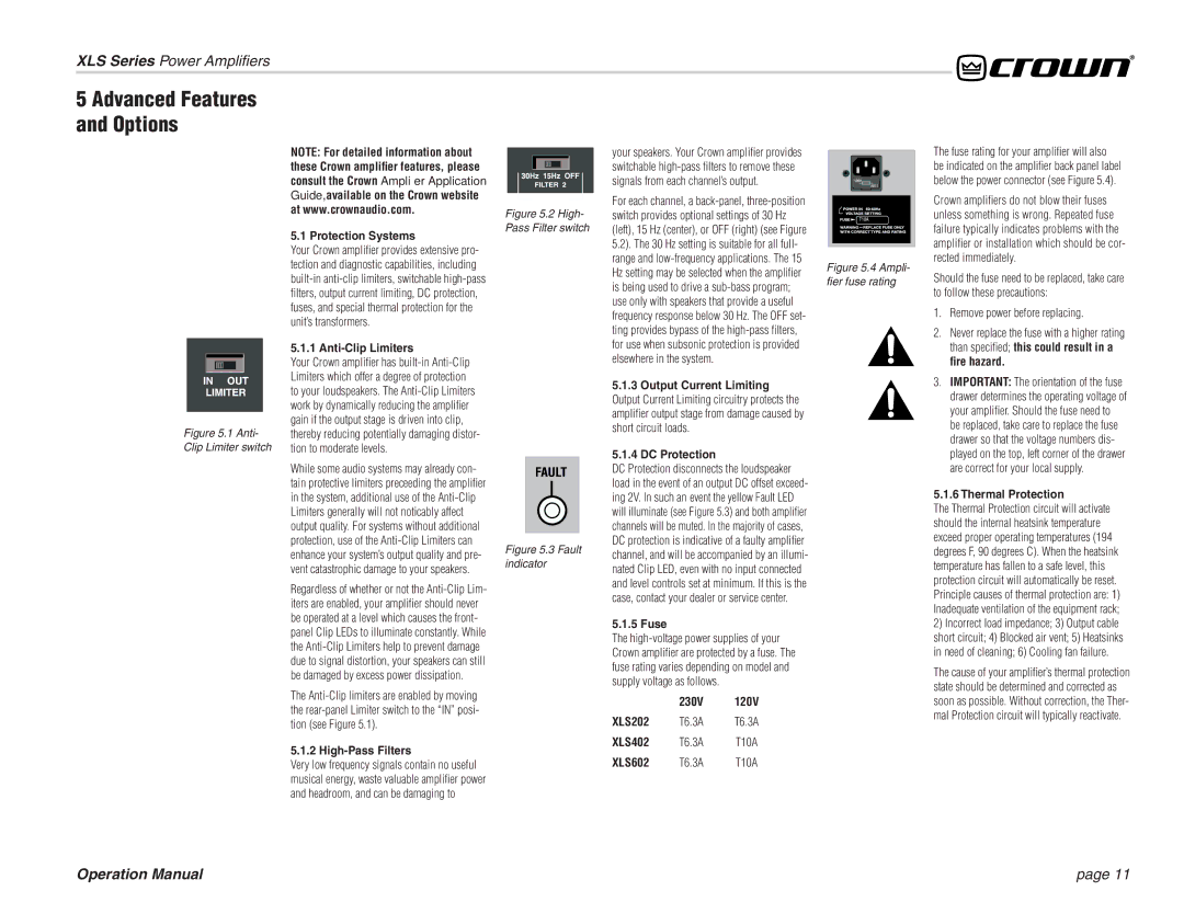
Figure 5.1 Anti-

Clip Limiter switch

NOTE: For detailed information about these Crown amplifier features, please consult the Crown Amplifier Application Guide, available on the Crown website at www.crownaudio.com.

5.1 Protection Systems

Your Crown amplifi er provides extensive pro- tection and diagnostic capabilities, including built-in anti-clip limiters, switchable high-pass

lters, output current limiting, DC protection, fuses, and special thermal protection for the unit’s transformers.

5.1.1 Anti-Clip Limiters

Your Crown amplifi er has built-in Anti-Clip Limiters which offer a degree of protection to your loudspeakers. The Anti-Clip Limiters work by dynamically reducing the amplifi er gain if the output stage is driven into clip, thereby reducing potentially damaging distor- tion to moderate levels.

While some audio systems may already con- tain protective limiters preceeding the amplifi er in the system, additional use of the Anti-Clip Limiters generally will not noticably affect output quality. For systems without additional protection, use of the Anti-Clip Limiters can enhance your system’s output quality and pre- vent catastrophic damage to your speakers.

Regardless of whether or not the Anti-Clip Lim- iters are enabled, your amplifi er should never be operated at a level which causes the front- panel Clip LEDs to illuminate constantly. While the Anti-Clip Limiters help to prevent damage due to signal distortion, your speakers can still be damaged by excess power dissipation.

The Anti-Clip limiters are enabled by moving the rear-panel Limiter switch to the “IN” posi- tion (see Figure 5.1).

5.1.2 High-Pass Filters

Figure 5.2 High- Pass Filter switch

Figure 5.3 Fault indicator

your speakers. Your Crown amplifi er provides switchable high-pass fi lters to remove these signals from each channel’s output.

For each channel, a back-panel, three-position switch provides optional settings of 30 Hz (left), 15 Hz (center), or OFF (right) (see Figure 5.2). The 30 Hz setting is suitable for all full- range and low-frequency applications. The 15 Hz setting may be selected when the amplifi er is being used to drive a sub-bass program; use only with speakers that provide a useful frequency response below 30 Hz. The OFF set- ting provides bypass of the high-pass fi lters, for use when subsonic protection is provided elsewhere in the system.

5.1.3Output Current Limiting

Output Current Limiting circuitry protects the amplifi er output stage from damage caused by short circuit loads.

5.1.4DC Protection

DC Protection disconnects the loudspeaker load in the event of an output DC offset exceed- ing 2V. In such an event the yellow Fault LED will illuminate (see Figure 5.3) and both amplifi er channels will be muted. In the majority of cases, DC protection is indicative of a faulty amplifi er channel, and will be accompanied by an illumi- nated Clip LED, even with no input connected and level controls set at minimum. If this is the case, contact your dealer or service center.

5.1.5 Fuse

The high-voltage power supplies of your Crown amplifi er are protected by a fuse. The fuse rating varies depending on model and supply voltage as follows.

230V 120V

XLS202 T6.3A T6.3A

XLS402 T6.3A T10A

Figure 5.4 Ampli- fier fuse rating

The fuse rating for your amplifi er will also be indicated on the amplifi er back panel label below the power connector (see Figure 5.4).

Crown amplifi ers do not blow their fuses unless something is wrong. Repeated fuse failure typically indicates problems with the amplifi er or installation which should be cor- rected immediately.

Should the fuse need to be replaced, take care to follow these precautions:

1.Remove power before replacing.

2.Never replace the fuse with a higher rating than specifi ed; this could result in a fire hazard.

3.IMPORTANT: The orientation of the fuse drawer determines the operating voltage of your amplifi er. Should the fuse need to be replaced, take care to replace the fuse drawer so that the voltage numbers dis- played on the top, left corner of the drawer are correct for your local supply.

5.1.6 Thermal Protection

The Thermal Protection circuit will activate should the internal heatsink temperature exceed proper operating temperatures (194 degrees F, 90 degrees C). When the heatsink temperature has fallen to a safe level, this protection circuit will automatically be reset. Principle causes of thermal protection are: 1) Inadequate ventilation of the equipment rack;

2)Incorrect load impedance; 3) Output cable short circuit; 4) Blocked air vent; 5) Heatsinks in need of cleaning; 6) Cooling fan failure.

The cause of your amplifi er’s thermal protection state should be determined and corrected as soon as possible. Without correction, the Ther- mal Protection circuit will typically reactivate.

Very low frequency signals contain no useful

XLS602

T6.3A

T10A

musical energy, waste valuable amplifi er power and headroom, and can be damaging to

Operation Manual

page 11

Page 11
Image 11
Crown Audio XL Series 230V, XLS202 T6.3A T6.3A XLS402 T6.3A T10A, Remove power before replacing, XLS602, Anti-ClipLimiters