Manuals
/
Crown Boiler
/
Household Appliance
/
Boiler
Crown Boiler
BWC120 35b CUTTING VERTICAL TERMINAL, 35c COMPLETING VERTICAL TERMINAL INSTALLATION
Models:
BWC120
BWC070
BWC090
1
24
27
27
Download
27 pages
52.29 Kb
20
21
22
23
24
25
26
27
<
>
Install
Dimension
7 SNORKEL TERMINAL CONFIGURATION
C. Assembly of Crown 60/100mm Concentric Venting
Page 24
Image 24
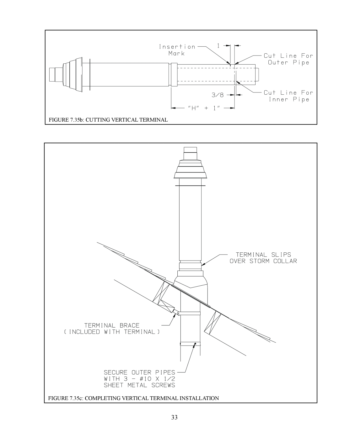
FIGURE 7.35b: CUTTING VERTICAL TERMINAL
FIGURE 7.35c: COMPLETING VERTICAL TERMINAL INSTALLATION
33
Page 23
Page 25
Page 24
Image 24
Page 23
Page 25
Contents
BWC070, BWC090, BWC120 Installation Manual Supplement June 12th
A. Vent System Design
VII Venting
Do not install the vent terminal directly over windows or doors
Example
90 elbow 1-1/2ft Straight Pipe 45Elbow
Uncut Terminal Section supplied with the boiler
Horizontal Terminal Clearance Requirements continued
FIGURE 7.2 HORIZONTAL CONCENTRIC VENTING VENT OPTION 1,3
FIGURE 7.3 HORIZONTAL TWIN PIPE VENTING VENT OPTION
TABLE 7.4a CROWN CONCENTRIC 60/100 VENT COMPONENTS VENT OPTION
TABLE 7.4b CROWN CONCENTRIC 80/125 VENT COMPONENTS VENT OPTIONS 3,6
TABLE 7.5 PERMISSIBLE STAINLESS STEEL VENT SYSTEMS
AND PRINCIPLE VENT COMPONENTS VENT OPTIONS 2
FIGURE 7.6c POSITIONING VENT TERMINAL UNDER OVERHANGS
FIGURE 7.7 SNORKEL TERMINAL CONFIGURATION
Pitch Crown horizontal concentric venting 5/8” per foot
Pitch Stainless steel venting 1/4” per foot
TABLE 7.8 VENT/ AIR INTAKE FITTING EQUIVALENT LENGTH
TABLE 7.9 SUMMARY OF VERTICAL VENTING OPTIONS
FIGURE 7.10 VERTICAL TWIN PIPE VENT SYSTEM VENT OPTION
FIGURE 7.11 VERTICAL CONCENTRIC VENT SYSTEM VENT OPTION
B. Removing an Existing Boiler From a Common Chimney
C. Assembly of Crown 60/100mm Concentric Venting
IMPORTANT - Skip to Section D for 80/125mm Concentric Vent Assembly
FIGURE 7.21 DIMENSION “L”
d Reinstall the inner pipe
FIGURE 7.22 CUTTING OUTER PIPE
FIGURE 7.23 CUTTING INNER PIPE
FIGURE 7.25 ATTACHING 60/100mm TERMINAL SECTION
D. Assembly of Crown 80/125mm Concentric Venting
IMPORTANT - See Section C for 60/100mm Concentric Vent Assembly
f Reinstall the inner pipe
b Remove the plastic inner pipe by pulling it out from the female end
d Make an insertion mark 1” from the male end of the outer pipe
FIGURE 7.31 CUTTING STRAIGHT PIPE
3 Joining Pipe
FIGURE 7.32a JOINING CUTTABLE PIPE
FIGURE 7.32b JOINING NON CUTTABLE PIPE
4 80/125mm Horizontal Terminal Installation
FIGURE 7.33a DIMENSION “L”, 80/125mm HORIZONTAL TERMINAL
FIGURE 7.33b CUTTING OUTER PIPE OF 80/125mm HORIZONTAL TERMINAL
FIGURE 7.33d COMPLETING 80/125mm HORIZONTAL TERMINAL INSTALLATION
FIGURE 7.33c CUTTING INNER PIPE OF 80/125mm HORIZONTAL TERMINAL
FIGURE 7.34 INSTALLATION OF SNORKEL TERMINAL
Key #
230541
Support Elbow
FIGURE 7.35a DIMENSION “H”
i Attach the Exhaust Terminal to the Terminal Elbow Figure
FIGURE 7.35c COMPLETING VERTICAL TERMINAL INSTALLATION
FIGURE 7.35b CUTTING VERTICAL TERMINAL
FIGURE 7.36 CHIMNEY CHASE INSTALLATION
E. Assembly of Stainless Steel Venting
3 Assembly of Metal-Fab Corr/Guard Vent System
a Corr/Guard General Notes Do not cut Corr/Guard vent components
g Replace and tighten the clamp on the vent collar
FIGURE 7.47 CORR/GUARD CONNECTION TO VENT COLLAR