6)Permitted Terminals for Vertical Venting -

Vent Option 5 - A straight termination is installed in the end of the vent pipe. Vent manufacturer part numbers for these screens are shown in Table 7.5. The air inlet terminal consists of a 180 degree elbow (or two 90 degree elbows) with a rodent screen as shown in Figure 7.10.

Vent Option 6 - Use Crown PN 230532 with the appropriate flashing (Table 7.4b)

7)Vertical Vent Terminal Locations (Vent Options 5,6) - Observe the following limitations on the location of all vertical vent terminals (see Figures 7.10, 7.11):

The top of the vent pipe must be at least 2 feet above any object located within 10 feet.

For Vent Option #5, the vertical distance between top of the vent and air inlet terminal openings must be at least 12”.

The bottom of the air inlet terminal must be at least 12” above the normal snow accumulation that can be expected on the roof. The terminal used in Vent Option #6 has a fixed distance above the storm collar of 19”. If a greater distance is needed to provide the clearance above the snow line, build a chase on the roof and mount the vertical terminal on top of the chase.

For Vent Option #5, the air intake terminal must be located on the roof and must be no further than 24” horizontally from the exhaust pipe.

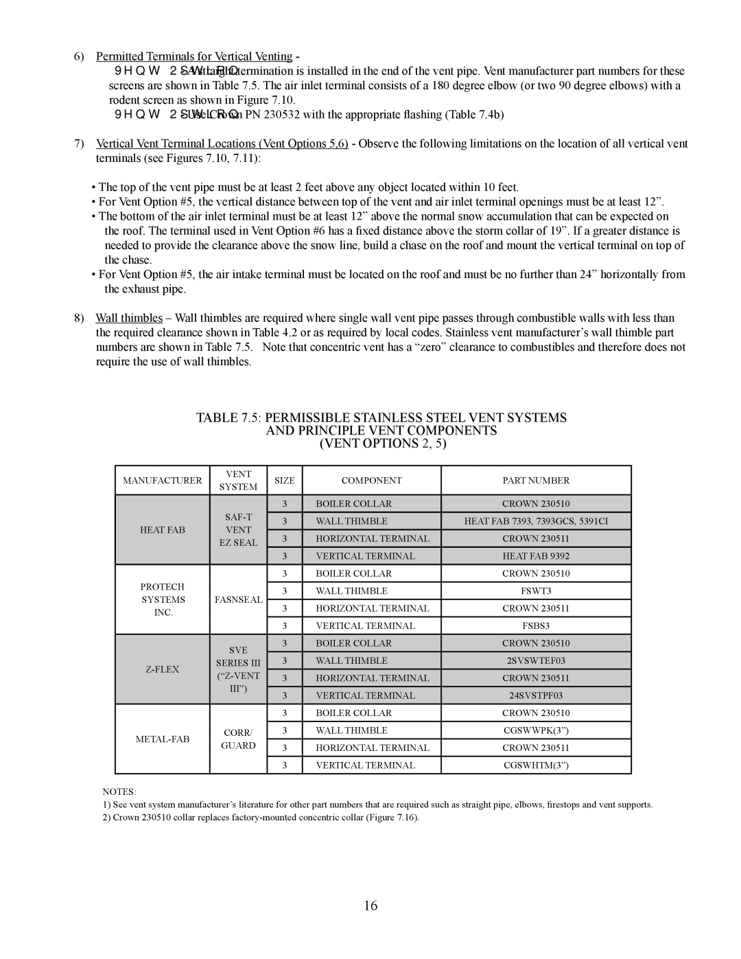
8)Wall thimbles – Wall thimbles are required where single wall vent pipe passes through combustible walls with less than the required clearance shown in Table 4.2 or as required by local codes. Stainless vent manufacturer’s wall thimble part numbers are shown in Table 7.5. Note that concentric vent has a “zero” clearance to combustibles and therefore does not require the use of wall thimbles.

TABLE 7.5: PERMISSIBLE STAINLESS STEEL VENT SYSTEMS

AND PRINCIPLE VENT COMPONENTS

(VENT OPTIONS 2, 5)

MANUFACTURER

VENT

SIZE

COMPONENT

PART NUMBER

SYSTEM


3

BOILER COLLAR

CROWN 230510


SAF-T


3

WALL THIMBLE

HEAT FAB 7393, 7393GCS, 5391CI

HEAT FAB

VENT


3

HORIZONTAL TERMINAL

CROWN 230511


EZ SEAL


3

VERTICAL TERMINAL

HEAT FAB 9392


3

BOILER COLLAR

CROWN 230510

PROTECH


3

WALL THIMBLE

FSWT3

SYSTEMS

FASNSEAL


3

HORIZONTAL TERMINAL

CROWN 230511

INC.


3

VERTICAL TERMINAL

FSBS3


SVE

3

BOILER COLLAR

CROWN 230510


3

WALL THIMBLE

2SVSWTEF03

Z-FLEX

SERIES III

(“Z-VENT

3

HORIZONTAL TERMINAL

CROWN 230511


III”)


3

VERTICAL TERMINAL

24SVSTPF03


3

BOILER COLLAR

CROWN 230510


METAL-FAB

CORR/

3

WALL THIMBLE

CGSWWPK(3”)

GUARD

3

HORIZONTAL TERMINAL

CROWN 230511


3

VERTICAL TERMINAL

CGSWHTM(3”)


NOTES:

1)See vent system manufacturer’s literature for other part numbers that are required such as straight pipe, elbows, firestops and vent supports.

2)Crown 230510 collar replaces factory-mounted concentric collar (Figure 7.16).

16

Page 7
Image 7
Crown Boiler BWC090, BWC120, BWC070 installation manual Manufacturer Vent Size Component Part Number

BWC120, BWC070, BWC090 specifications

Crown Boiler Company has established itself as a leader in the heating industry, providing reliable and efficient solutions for residential and commercial applications. Among their innovative product line, the BWC series, which includes the BWC120, BWC070, and BWC090 models, showcases advanced technology and design features that cater to the diverse needs of consumers.

The BWC series is designed to deliver exceptional heating performance while being user-friendly and efficient. One of the main features of these models is their compact design, making them suitable for installations in tight spaces, such as basements and utility rooms. This space-saving advantage does not compromise their power or heating capacity, as each model is engineered to handle a variety of heating demands.

A prominent technology in the BWC series is the high-efficiency, modulating condensing design. This allows the boilers to adjust their output based on the heating requirements of the space, leading to significant energy savings. By utilizing a variable-speed blower and an integrated control system, these boilers can operate at lower heating outputs when the demand is lower, ultimately improving overall efficiency and reducing fuel costs.

The BWC120, with an output of 120 MBH, is ideal for larger homes or light commercial applications, providing robust heating capabilities. The BWC090 offers a slightly lower output at 90 MBH, catering to moderately sized homes. Meanwhile, the BWC070 targets smaller residential settings with an output of 70 MBH, ensuring that there is a fitting option for a variety of heating needs.

In addition to their efficiency and compact design, the BWC models are equipped with advanced safety features, including built-in temperature and pressure relief valves. These safety measures give homeowners peace of mind, knowing that their heating system is operating safely and reliably.

Durability is another characteristic that defines the BWC series. Constructed with high-quality materials and designed to withstand the rigors of everyday use, these boilers are built to last. The easy-to-service construction ensures that routine maintenance is straightforward, thereby enhancing longevity and reliability.

In summary, the Crown Boiler BWC120, BWC070, and BWC090 models combine efficiency, advanced technology, and safety features, making them an excellent choice for anyone in the market for dependable heating solutions. Their adaptability to various heating needs, along with their space-saving designs, makes them suitable for a wide range of applications, ensuring comfort and reliability for years to come.