6)Vertical Terminal Installation - In addition to the vertical terminal, either a Flat Roof Flashing (80/125 PN 230533, 100/150 PN 230571) or Sloped Roof Flashing (80/125 PN 230535, 100/150 PN 230572) is required for this installation.

a)Determine the center line of the terminal location on the roof. If the roof is flat, cut a 5-1/2” diameter hole for the 80/125 terminal and a 6-1/2” diameter hole for the 100/150 terminal. If the roof is sloped, cut a hole large enough for the terminal to pass through the roof while remaining plumb. Caution: If the boiler is installed directly under the hole, cover it while cutting the hole to prevent saw dust and other debris from falling into the boiler.

b)Install the roof flashing using standard practice for the roofing system on the structure.

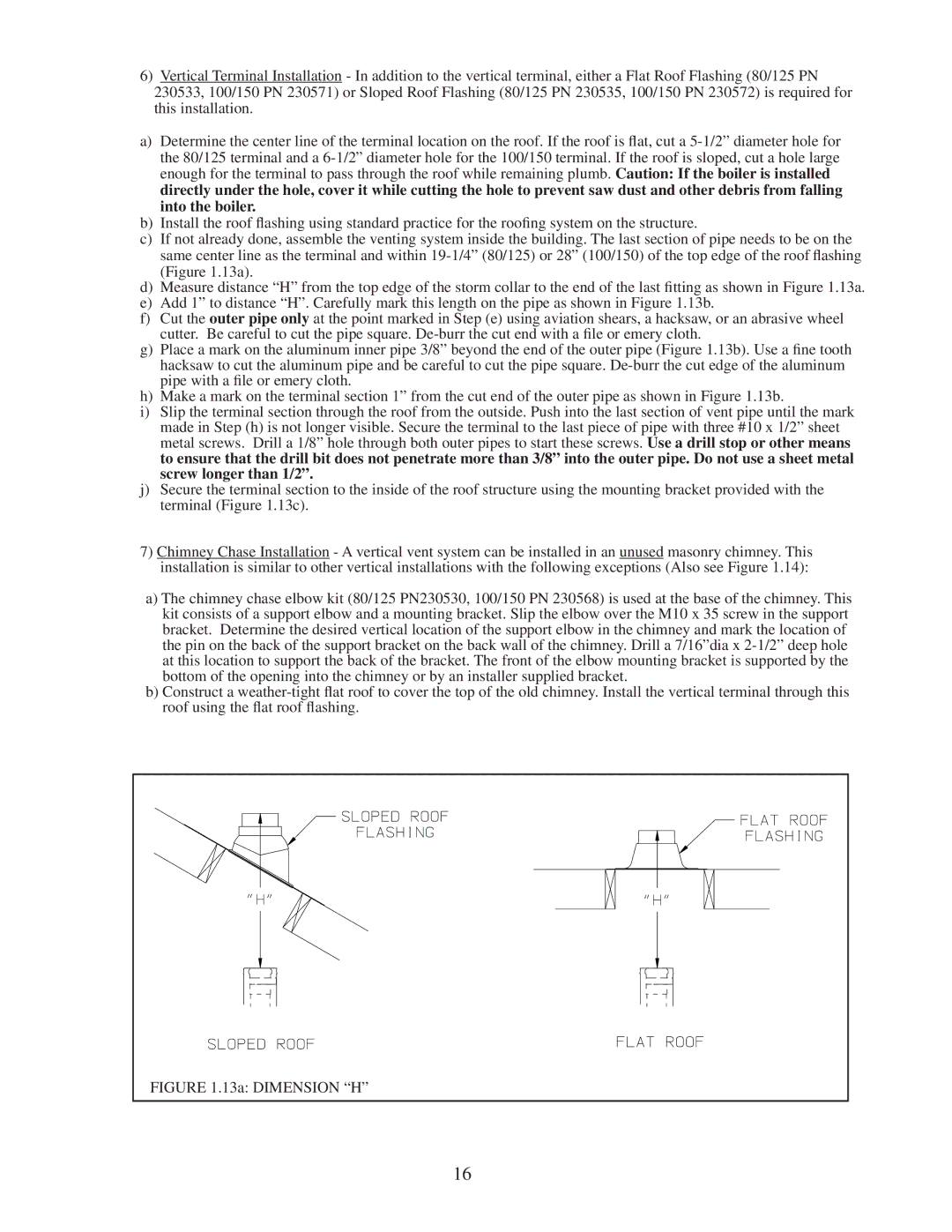
c)If not already done, assemble the venting system inside the building. The last section of pipe needs to be on the same center line as the terminal and within 19-1/4” (80/125) or 28” (100/150) of the top edge of the roof flashing (Figure 1.13a).

d)Measure distance “H” from the top edge of the storm collar to the end of the last fitting as shown in Figure 1.13a.

e)Add 1” to distance “H”. Carefully mark this length on the pipe as shown in Figure 1.13b.

f)Cut the outer pipe only at the point marked in Step (e) using aviation shears, a hacksaw, or an abrasive wheel cutter. Be careful to cut the pipe square. De-burr the cut end with a file or emery cloth.

g)Place a mark on the aluminum inner pipe 3/8” beyond the end of the outer pipe (Figure 1.13b). Use a fine tooth hacksaw to cut the aluminum pipe and be careful to cut the pipe square. De-burr the cut edge of the aluminum pipe with a file or emery cloth.

h)Make a mark on the terminal section 1” from the cut end of the outer pipe as shown in Figure 1.13b.

i)Slip the terminal section through the roof from the outside. Push into the last section of vent pipe until the mark made in Step (h) is not longer visible. Secure the terminal to the last piece of pipe with three #10 x 1/2” sheet metal screws. Drill a 1/8” hole through both outer pipes to start these screws. Use a drill stop or other means to ensure that the drill bit does not penetrate more than 3/8” into the outer pipe. Do not use a sheet metal screw longer than 1/2”.

j)Secure the terminal section to the inside of the roof structure using the mounting bracket provided with the terminal (Figure 1.13c).

7)Chimney Chase Installation - A vertical vent system can be installed in an unused masonry chimney. This installation is similar to other vertical installations with the following exceptions (Also see Figure 1.14):

a)The chimney chase elbow kit (80/125 PN230530, 100/150 PN 230568) is used at the base of the chimney. This kit consists of a support elbow and a mounting bracket. Slip the elbow over the M10 x 35 screw in the support bracket. Determine the desired vertical location of the support elbow in the chimney and mark the location of the pin on the back of the support bracket on the back wall of the chimney. Drill a 7/16”dia x 2-1/2” deep hole at this location to support the back of the bracket. The front of the elbow mounting bracket is supported by the bottom of the opening into the chimney or by an installer supplied bracket.

b)Construct a weather-tight flat roof to cover the top of the old chimney. Install the vertical terminal through this roof using the flat roof flashing.

FIGURE 1.13a: DIMENSION “H”

16

Page 18
Image 18
Crown Boiler BWC150/225 installation instructions 13a Dimension H

BWC150/225 specifications

The Crown Boiler BWC150/225 is a highly efficient and reliable hydronic heating system designed for both residential and commercial applications. Known for its advanced engineering, this boiler delivers exceptional performance while adhering to strict emission standards. Its versatility and durability make it a popular choice among homeowners and professionals alike.

One of the key features of the BWC150/225 model is its dual-fuel capability, allowing the user to operate the boiler on either natural gas or propane. This flexibility not only ensures convenience but also enhances energy efficiency. The boiler is equipped with a powerful 150,000 BTU input capacity for the BWC150 variant and 225,000 BTU for the BWC225, making it capable of heating larger spaces efficiently.

The crown boiler utilizes a fire-tube heat exchanger, which is designed to maximize heat transfer while minimizing the amount of energy lost during operation. This innovative design allows for a higher thermal efficiency rate compared to traditional designs. With an efficiency rating exceeding 90%, the BWC series can significantly lower heating costs, making it an economically sound investment.

Additionally, the BWC model features a fully modulating gas valve that adjusts the heat output based on the demand. This system not only improves comfort by maintaining consistent temperatures but also reduces energy consumption. It is also designed with advanced safety features, including an integrated low-water cutoff and flame rollout protection, ensuring safe operation under various conditions.

Another noteworthy characteristic of the Crown Boiler BWC150/225 is its user-friendly digital control panel. The easy-to-read display provides users with vital information such as temperature settings and system diagnostics, simplifying both operation and maintenance. The compact design of the unit allows for easy installation in tight spaces, making it suitable for various home layouts.

In summary, the Crown Boiler BWC150/225 stands out for its advanced features, energy efficiency, and safety technologies. With its dual-fuel capability, fire-tube heat exchanger, and user-friendly interface, it is an optimal choice for those seeking a robust and reliable heating solution. Whether for residential or commercial purposes, this model offers the performance and convenience that modern users require.