User’s Manual for CyberShield
CS50U48V
CS24U12V
CyberShield UPSs are designed to provide a local power solution for cable telephony, wireless local loop (WLL), and fiber to the home (FTTH) broadband equipment.
IMPORTANT SAFETY WARNINGS (SAVE THESE INSTRUCTIONS)
This manual contains important instructions regarding the installation and operation of this device. Read this manual thoroughly before attempting to unpack , install or operate this device
CAUTION! The battery can energize hazardous live parts inside even when the AC input power is disconnected.
CAUTION! To prevent the risk of fire or electric shock, install in a temperature and humidity controlled indoor area, free of conductive contaminants. (Please see specifications for acceptable temperature and humidity range).
CAUTION! To reduce the risk of electric shock, do not remove the cover, except to service the battery. No user serviceable parts inside, except for the battery.
CAUTION! To avoid electric shock, turn off the unit and unplug it from the AC power source before servicing the battery or installing a computer component.
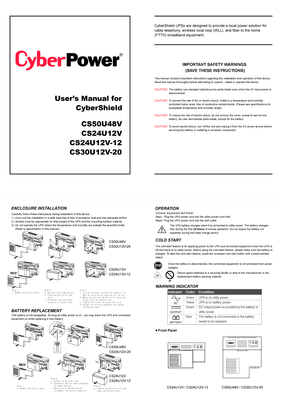
ENCLOSURE INSTALLATION
Carefully follow these instructions during installation of this device:
1.) Carry out the installation in a safe area that is free of excessive dust and has adequate airflow.
2.) Screws must be appropriate for total weight of the UPS and the mounting surface material.
3.) Do not operate the UPS where the temperature and humidity are outside the specified limits. (Refer to specification in this manual.)
CS50U48V
| CS24U12V | |
Battery Cover | ||
Release Tab | ||
|
OPERATION
Connect: Equipment and Power
Step1. Plug the UPS power cord into the utility power cord inlet
Step2. Plug the UPS power cord into the wall outlet.
The UPS battery charges when it is connected to utility power. The battery charges fully during the first 24 hours of normal operation. Do not expect full battery run capability during this initial charge period.
COLD START
The cold start feature is for applying power to the UPS and connected equipment when the UPS is off and there is no utility power. Before using the cold start feature, please make sure the battery is charged. To start the cold start feature, press the recessed cold start button with a small pointed object.
Once the battery is disconnected, the connected equipment is not protected from power outages.
Deliver spent batteries to a recycling facility or ship to the manufacturer in the replacement battery packing material.
Step 1: | Step 2: | Step 3: |
|
a. Remove the battery cover. | a. Unstrap strap from battery. | a. Use the | enclosed installation template to |
| b. Slide battery off of the | mark an installation location for the unit. | |
| shelf. | b. Mount the unit on the wall with 2 mounting | |
| c. Disconnect battery cable | screws into the keyhole slots. | |
| connector at chassis end. | c. Tighten the screws to secure the units. | |
|
| d. Connect the battery connector and replace | |
|
| the battery back. | |
BATTERY REPLACEMENT
This battery is
WARNING INDICATOR
|
| Indicator Color | Condition | |
|
|
| Green | UPS is on utility power. |
|
|
| Yellow | UPS is on battery power. |
|
|
|
|
|
|
|
| Green | DC output power is provided by the battery or |
|
|
|
| utility power. |
|
|
|
|
|
|
|
| Red | The battery is not connected or the battery |
|
|
|
| needs to be replaced. |
|
|
| ||
Front Panel |
| |||
|
|
| |
BATTERY |
|
|
|
HERE | CS50U48V |
|
|
| AC | OUTPUT BATTERY | |
|
|
|
Battery Cover
Release Tab
| Step 2: | CS24U12V |
|
|
| ||
| a. Loosen the battery strap. |
| |
| b. Disconnect battery cable connector |
|
|
Step 1: | to remove battery. | Step 3: | CS24U12V / |
a. Remove the battery cover. | c. Replace with new battery and | a. Tighten the battery strip and | |
| close the battery cover. |
|
AC OUTPUT BATTERY |
CS50U48V / |