eu.cyberpowersystems.com
Professional Tower UPS
PP1500E/PP2200E
User’s Manual
SAFETY WARNINGS
(SAVE THESE INSTRUCTIONS)
This manual contains important safety instructions. Please read and follow all instructions carefully during installation and operation of the unit. Read this manual thoroughly before attempting to unpack, install, or operate your UPS.
This equipment can be operated by any individuals with no previous training.
The
During the installation of this equipment it should be assured that the sum of the leakage currents of the UPS and the connected loads does not exceed 3.5mA.
Attention, hazardous through electric shock. Also with disconnection of this unit from the mains, hazardous voltage still may be accessible through supply from battery. The battery supply should be therefore disconnected in the plus and minus pole at the quick connectors of the battery when maintenance or service work inside the UPS is necessary.
Do not dispose of batteries in a fire, the battery may explode.
Do not open or mutilate the battery or batteries, released electrolyte is harmful to the skin and eyes.
INSTALLING YOUR UPS SYSTEM
UNPACKING
Inspect the UPS upon receipt. The box should contain the following:
UPS Unit¯1; PowerPanel® Software Disk¯1; PowerPanel® Business Edition Software Disk¯1; Serial Interface Cable
HOW TO DETERMINE THE POWER REQUIREMENTS OF YOUR EQUIPMENT
1.Insure that the equipment plugged into the battery
2.If the power requirements of your equipment are listed in units other than
TO ESTIMATE POWER REQUIREMENTS
1. |
| Watts (W) x 2.0 = |
| VA or |
| Amps (A) x 230 = |
| VA |
2.Add the totals up for all pieces of equipment and multiply this total by 0.6 to calculate actual requirements. There are many factors that can affect the amount of power that your computer system will require. The total load that you will be placing on the
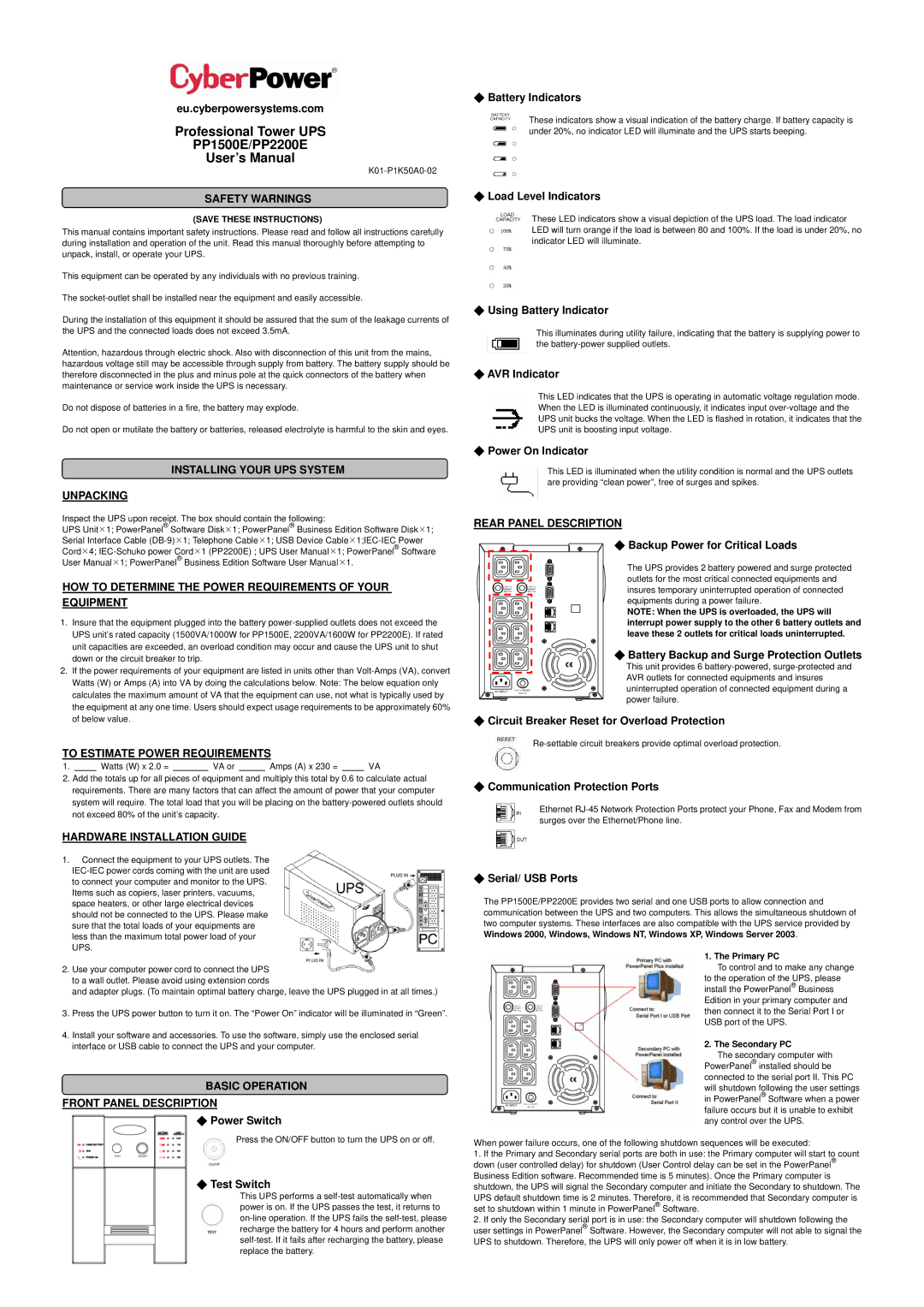
HARDWARE INSTALLATION GUIDE
1.Connect the equipment to your UPS outlets. The
2.Use your computer power cord to connect the UPS to a wall outlet. Please avoid using extension cords
and adapter plugs. (To maintain optimal battery charge, leave the UPS plugged in at all times.)
3.Press the UPS power button to turn it on. The “Power On” indicator will be illuminated in “Green”.
4.Install your software and accessories. To use the software, simply use the enclosed serial interface or USB cable to connect the UPS and your computer.
BASIC OPERATION
FRONT PANEL DESCRIPTION
◆Power Switch
Press the ON/OFF button to turn the UPS on or off.
◆Test Switch
This UPS performs a
◆Battery Indicators
These indicators show a visual indication of the battery charge. If battery capacity is under 20%, no indicator LED will illuminate and the UPS starts beeping.
◆Load Level Indicators
These LED indicators show a visual depiction of the UPS load. The load indicator LED will turn orange if the load is between 80 and 100%. If the load is under 20%, no indicator LED will illuminate.
◆Using Battery Indicator
This illuminates during utility failure, indicating that the battery is supplying power to the
◆AVR Indicator
This LED indicates that the UPS is operating in automatic voltage regulation mode. When the LED is illuminated continuously, it indicates input
◆Power On Indicator
This LED is illuminated when the utility condition is normal and the UPS outlets are providing “clean power”, free of surges and spikes.
REAR PANEL DESCRIPTION
◆Backup Power for Critical Loads
The UPS provides 2 battery powered and surge protected outlets for the most critical connected equipments and insures temporary uninterrupted operation of connected equipments during a power failure.
NOTE: When the UPS is overloaded, the UPS will interrupt power supply to the other 6 battery outlets and leave these 2 outlets for critical loads uninterrupted.
◆Battery Backup and Surge Protection Outlets
This unit provides 6
◆Circuit Breaker Reset for Overload Protection
◆Communication Protection Ports
Ethernet
◆Serial/ USB Ports
The PP1500E/PP2200E provides two serial and one USB ports to allow connection and communication between the UPS and two computers. This allows the simultaneous shutdown of two computer systems. These interfaces are also compatible with the UPS service provided by Windows 2000, Windows, Windows NT, Windows XP, Windows Server 2003.
1. The Primary PC
To control and to make any change to the operation of the UPS, please install the PowerPanel® Business Edition in your primary computer and then connect it to the Serial Port I or USB port of the UPS.
2. The Secondary PC
The secondary computer with PowerPanel® installed should be connected to the serial port II. This PC will shutdown following the user settings in PowerPanel® Software when a power failure occurs but it is unable to exhibit any control over the UPS.
When power failure occurs, one of the following shutdown sequences will be executed:
1.If the Primary and Secondary serial ports are both in use: the Primary computer will start to count down (user controlled delay) for shutdown (User Control delay can be set in the PowerPanel® Business Edition software. Recommended time is 5 minutes). Once the Primary computer is shutdown, the UPS will signal the Secondary computer and initiate the Secondary to shutdown. The
UPS default shutdown time is 2 minutes. Therefore, it is recommended that Secondary computer is set to shutdown within 1 minute in PowerPanel® Software.
2.If only the Secondary serial port is in use: the Secondary computer will shutdown following the user settings in PowerPanel® Software. However, the Secondary computer will not able to signal the UPS to shutdown. Therefore, the UPS will only power off when it is in low battery.