LANIER – 1/3rd Scale Laser 200 ARF -INSTRUCTIONS
46.Installthetailwheelon theaxle,then secure with thesm allwheelcollarand setscrew .Use som ethread lock on thescrew .
47.Locatethehardpointsinthetailsurfacesforthe tailbracewires.Piercethecoveringwithasharp blade.Putaslightbend in (12)ofthetailwire brackets,then installthem in thehorizontaland verticalstabilizersasshown,with abracketon both sidesofthesurfaces.
48.
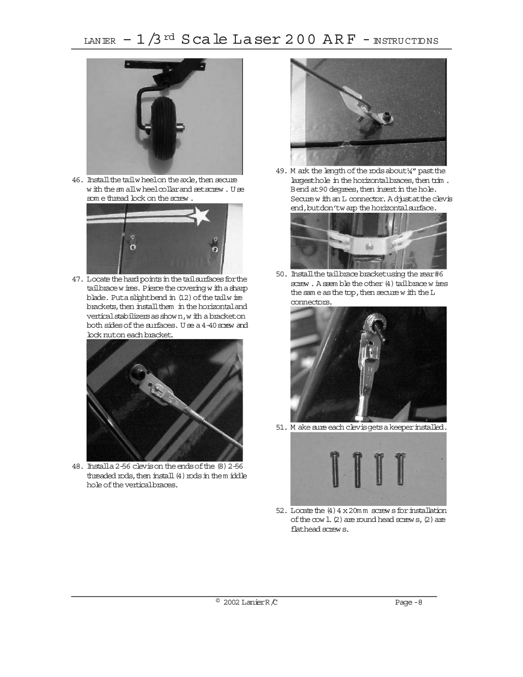
49.M ark thelength oftherodsabout¼”pastthe largesthole in thehorizontalbraces,then trim . Bend at90 degrees,then insertin thehole.
Securewith an L connector.Adjustattheclevis end,butdon’twarp thehorizontalsurface.
50.Installthetailbracebracketusing therear#6 screw . Assem bletheother(4)tailbracewires thesam easthetop,then securewith theL connectors.
51. M akesureeach clevisgetsakeeperinstalled.
52.Locatethe(4)4x20m m screwsforinstallation ofthecowl.(2)areround head screws,(2)are flathead screws.
© 2002 LanierR/C |