LANIER – 1/3rd Scale Laser 200 ARF -INSTRUCTIONS
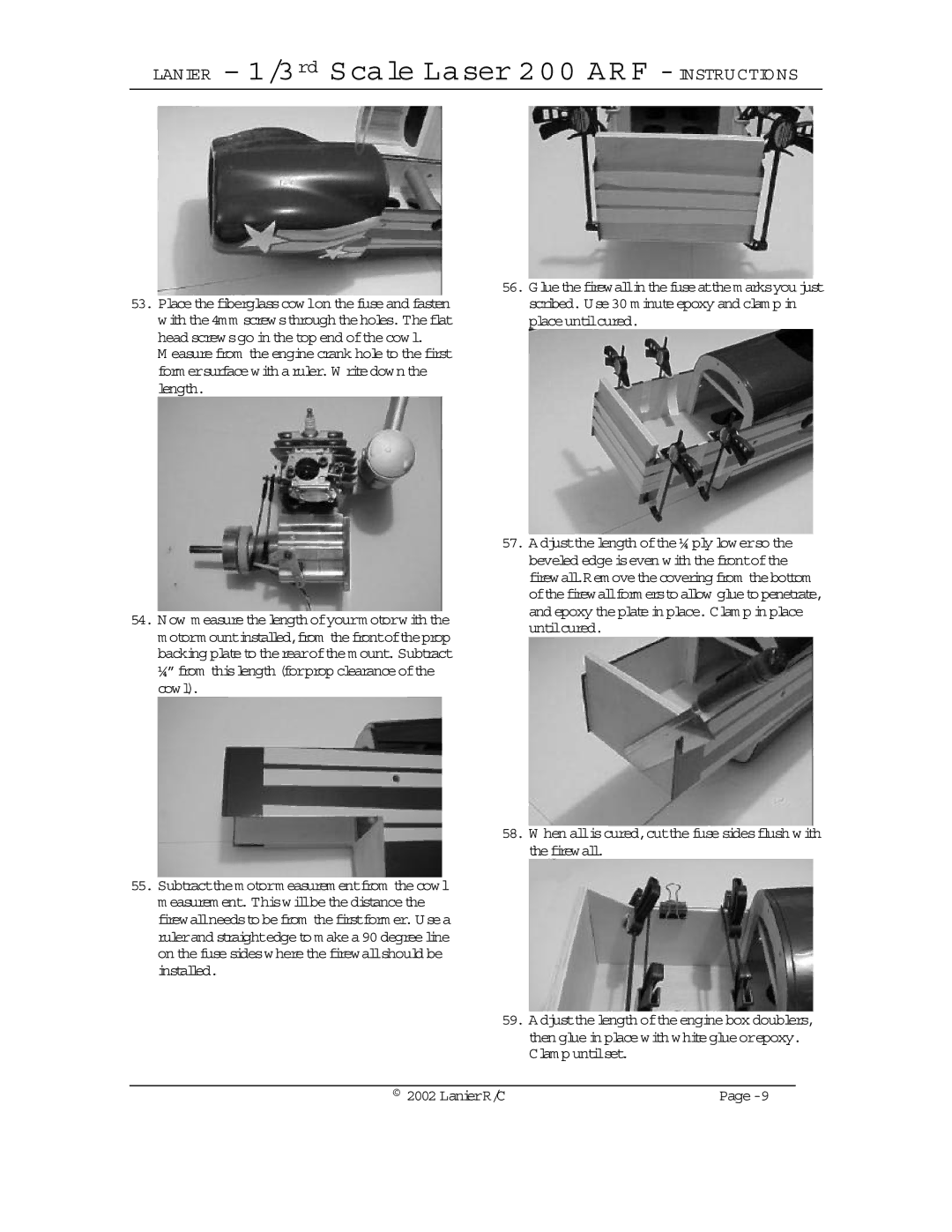
53.Placethefiberglasscowlon thefuseand fasten with the4mm screwsthroughtheholes.Theflat head screwsgo in thetop end ofthecowl.
M easurefrom theenginecrank holeto thefirst form ersurfacewith aruler.W ritedown the length.
54.Now m easurethelength ofyourm otorwith the m otorm ountinstalled,from thefrontoftheprop backing plateto therearofthem ount.Subtract ¼”from thislength (forprop clearanceofthe cowl).
55.Subtractthem otorm easurem entfrom thecowl m easurem ent. Thiswillbethedistancethe firewallneedsto befrom thefirstform er.Usea rulerand straightedgeto m akea90 degreeline on thefusesideswherethefirewallshould be installed.
56.Gluethefirewallinthefuseatthem arksyoujust scribed. Use30 m inuteepoxy and clam p in placeuntilcured.
57.Adjustthelength ofthe¼ ply lowerso the beveled edgeiseven with thefrontofthe firewall.Rem ovethecovering from thebottom ofthefirewallform erstoallow gluetopenetrate, and epoxy theplatein place.Clam p in place untilcured.
58.W hen alliscured,cutthefusesidesflush with thefirewall.
59.Adjustthelength oftheenginebox doublers, then gluein placewith whiteglueorepoxy. Clam p untilset.
© 2002 LanierR/C |
|