LANIER – 1/3rd Scale Laser 200 ARF -INSTRUCTIONS
firewall,behind theblind nuts.
69.Drill(5)3/32”holeson each sideofthefirewall, through thefusesidesabout1”deep. Pressa wood toothpick into thehole,then cutoffflush with som ewiresnips. Apply severaldropsof thin CA on each toothpick.
70.M ark on thefirewallthelocation wherethe throttlecontrolrod should passthrough. Drill them arked holewith a1/8”aircraftdrillbit.
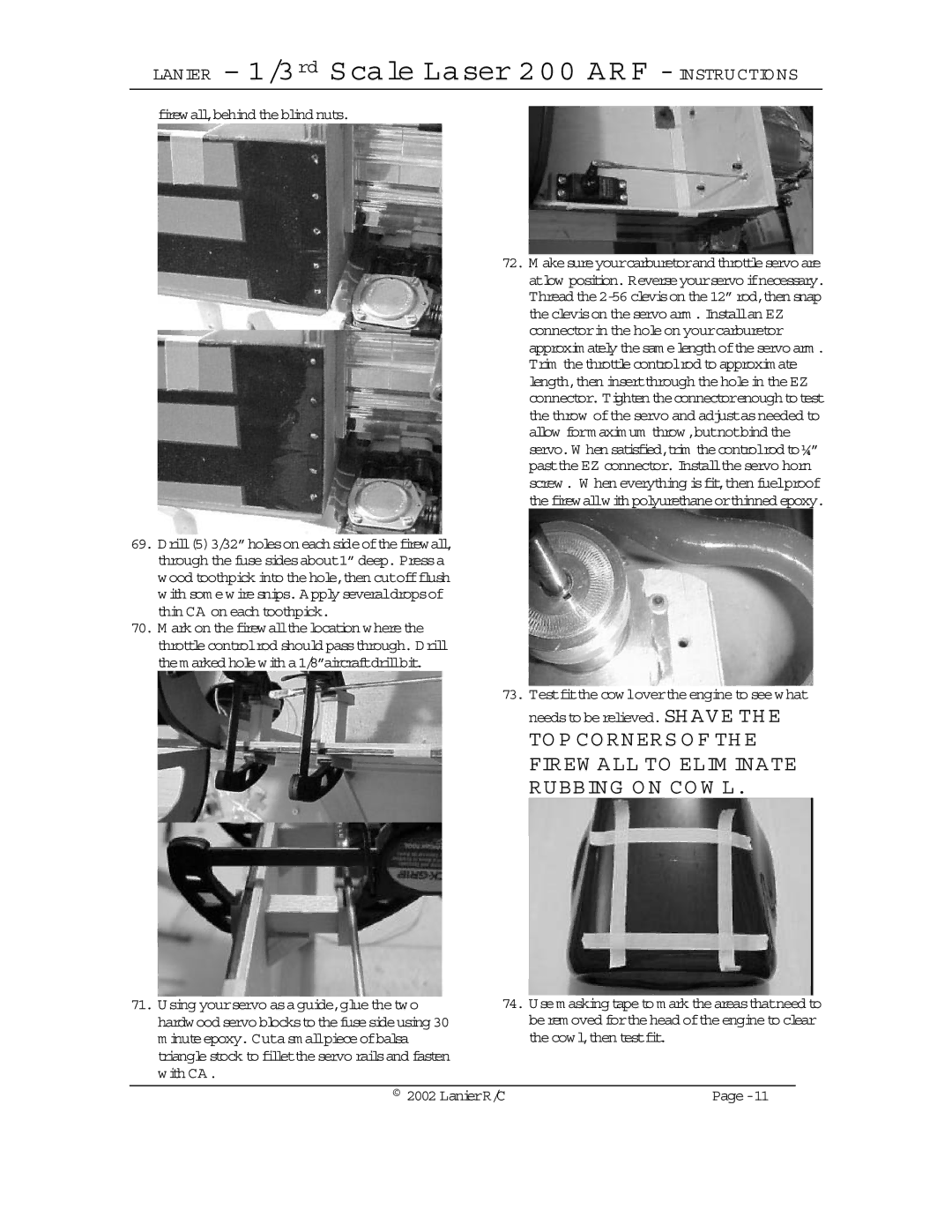
72.M akesureyourcarburetorandthrottleservoare atlow position.Reverseyourservoifnecessary. Thread
73. Testfitthecowlovertheengineto seewhat
needsto berelieved. SH AVE TH E
TO P CO RNERS O F TH E FIREW ALL TO ELIM INATE RUBBING O N CO W L.
71.Using yourservo asaguide,gluethetwo hardwoodservoblockstothefusesideusing30 m inuteepoxy.Cutasm allpieceofbalsa trianglestock to fillettheservo railsand fasten with CA.
74.Usem asking tapeto m ark theareasthatneed to berem oved forthehead oftheengineto clear thecowl,then testfit.
© 2002 LanierR/C |