LANIER – 1/3rd Scale Laser 200 ARF -INSTRUCTIONS
37.Useastraightedgeto align theelevatorand ruddercontrolhornslocation.
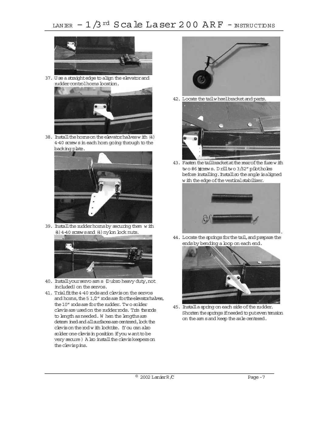
42. Locatethetailwheelbracketand parts.
38.Installthehornson theelevatorhalveswith (4)
39.Installtherudderhornsby securing them with
40.Installyourservo arm s (Dubro heavy duty,not included)on theservos.
41.Trialfitthe4-40 rodsand clevison the servos
and horns,the5 1/2”rodsarefortheelevatorhalves, the10”rodsarefortherudder. Two solder clevisareusedon therudderrods. Trim therods to length asneeded. W hen thelengthsare determ inedandallsurfacesarecentered,lockthe clevison therod with locktite.(You can also solderoneclevisin position ifyou wanttobe very secure) Also installthecleviskeeperson theclevispins.
43.Fasten thetailbracketattherearofthefusewith two #6 ½screws. Drilltwo 3/32”pilotholes beforeinstalling.Installso theangleisaligned with theedgeoftheverticalstabilizer.
 .
.
44.Locatethespringsforthetail,and preparethe endsby bending aloop on each end.
45.Installaspring on each sideoftherudder. Shortenthespringsifneededtoputeventension on thearm sand keep theaxlecentered.
© 2002 LanierR/C |