Comparison of Standard USB Request “Get Descriptor”
Conventional Method
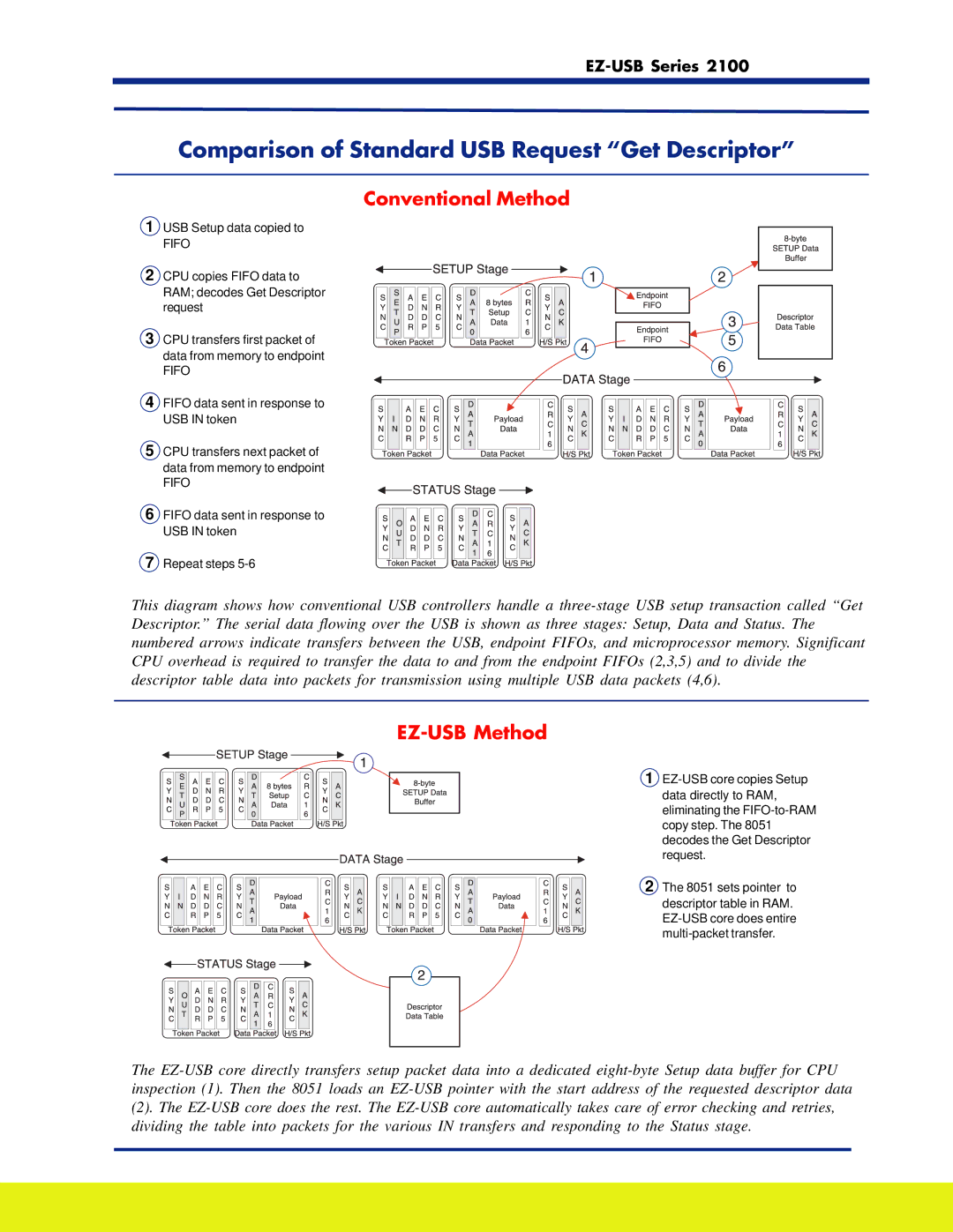
1USB Setup data copied to
FIFO
2 CPU copies FIFO data to RAM; decodes Get Descriptor request
3 CPU transfers first packet of data from memory to endpoint
FIFO
4 FIFO data sent in response to USB IN token
5 CPU transfers next packet of data from memory to endpoint
FIFO
6 FIFO data sent in response to USB IN token
7 Repeat steps 5-6
This diagram shows how conventional USB controllers handle a three-stage USB setup transaction called “Get Descriptor.” The serial data flowing over the USB is shown as three stages: Setup, Data and Status. The numbered arrows indicate transfers between the USB, endpoint FIFOs, and microprocessor memory. Significant CPU overhead is required to transfer the data to and from the endpoint FIFOs (2,3,5) and to divide the descriptor table data into packets for transmission using multiple USB data packets (4,6).
EZ-USB Method
1 EZ-USB core copies Setup data directly to RAM, eliminating the FIFO-to-RAM copy step. The 8051 decodes the Get Descriptor request.
2 The 8051 sets pointer to descriptor table in RAM. EZ-USB core does entire multi-packet transfer.
The EZ-USB core directly transfers setup packet data into a dedicated eight-byte Setup data buffer for CPU inspection (1). Then the 8051 loads an EZ-USB pointer with the start address of the requested descriptor data
(2). The EZ-USB core does the rest. The EZ-USB core automatically takes care of error checking and retries, dividing the table into packets for the various IN transfers and responding to the Status stage.