|
|
|
|
|
| FS781/82/84 |
|
|
|
|
|
|
|
|
|
Table 4. Modulation Rate Divider Ratios |
|
| |||||
|
|
|
|
|
|
|
|
S1 |
| S0 |
|
| Input Frequency Range (MHz) | Modulation Divider Number |
|
|
|
|
|
|
|
|
|
0 |
| 0 |
|
| 6 to 16 | 120 |
|
|
|
|
|
|
|
|
|
0 |
| 1 |
|
| 16 to 32 | 240 |
|
|
|
|
|
|
|
|
|
1 |
| 0 |
|
| 32 to 66 | 480 |
|
|
|
|
|
|
|
|
|
1 |
| 1 |
|
| 66 to 82 | 720 |
|
|
|
|
|
|
|
|
|
SSCG Modulation Profile
The digital control inputs S0 and S1 determine the modulation frequency of FS781/2/4 products. The input frequency is divided by a fixed number, depending on the operating range that is selected. The modulation frequency of the FS78x can be determined from Table 4. To compute the modulation frequency, determine the values of S0 and S1, and find the modulation divider number in Table 4.
quently, higher energy peaks. Regulatory agencies test electronic equipment by the amount of peak energy radiated from the equipment. By reducing the peak energy at the funda- mental and harmonic frequencies, the equipment under test is able to satisfy agency requirements for EMI. Conventional methods of reducing EMI have been to use shielding, filtering,
Theory of Operation
The FS781/82/84 devices are
EMI
All clocks generate unwanted energy in their harmonics. Conventional digital clocks are square waves with a duty cycle that is very close to 50%. Because of the 50/50 duty cycle, digital clocks generate most of their harmonic energy in the odd harmonics (e.g., third, fifth, seventh). It is possible to reduce the amount of energy contained in the fundamental and harmonics by increasing the bandwidth of the funda- mental clock frequency. Conventional digital clocks have a very high Q factor, which means that all of the energy at that frequency is concentrated in a very narrow bandwidth, conse-
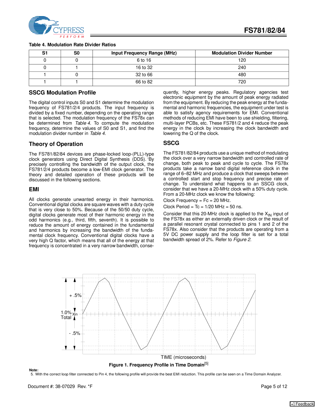
SSCG
The FS781/82/84 products use a unique method of modulating the clock over a very narrow bandwidth and controlled rate of change, both peak to peak and cycle to cycle. The FS78x products take a narrow band digital reference clock in the range of
Clock Frequency = Fc = 20 MHz. Clock Period = Tc = 1/20 MHz = 50 ns.
Consider that this
+ .5% |
1.0% Xin |
Total |
TIME (microseconds)
Figure 1. Frequency Profile in Time Domain[5]
Note:
5. With the correct loop filter connected to Pin 4, the following profile will provide the best EMI reduction. This profile can be seen on a Time Domain Analyzer.
Document #: | Page 5 of 12 |
[+] Feedback