Chapter 2 Hardware Installation
2.1. Panel Layout
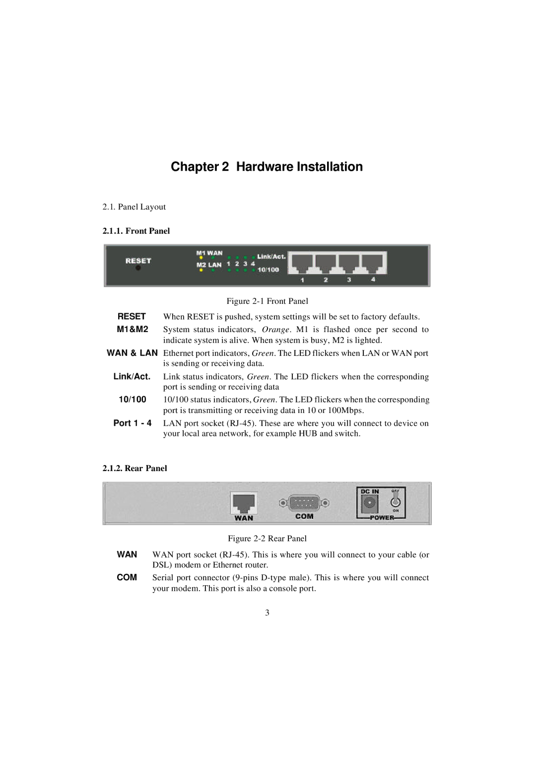
2.1.1. Front Panel
Figure 2-1 Front Panel
RESET When RESET is pushed, system settings will be set to factory defaults. M1&M2 System status indicators, Orange. M1 is flashed once per second to
indicate system is alive. When system is busy, M2 is lighted.
WAN & LAN Ethernet port indicators, Green. The LED flickers when LAN or WAN port is sending or receiving data.
Link/Act. Link status indicators, Green. The LED flickers when the corresponding port is sending or receiving data
10/100 10/100 status indicators, Green. The LED flickers when the corresponding port is transmitting or receiving data in 10 or 100Mbps.
Port 1 - 4 LAN port socket (RJ-45). These are where you will connect to device on your local area network, for example HUB and switch.
2.1.2. Rear Panel
Figure 2-2 Rear Panel
WAN WAN port socket (RJ-45). This is where you will connect to your cable (or DSL) modem or Ethernet router.
COM Serial port connector (9-pins D-type male). This is where you will connect your modem. This port is also a console port.
3