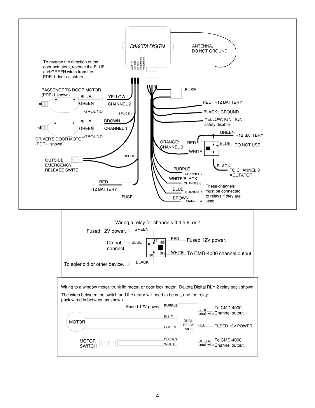
CMD-4000 specifications
The Dakota Digital CMD-4000 is an innovative gauge system designed for automotive enthusiasts seeking advanced monitoring and customization for their vehicles. This cutting-edge digital display offers a comprehensive suite of features, technologies, and characteristics that enhance both functionality and aesthetics.One of the standout features of the CMD-4000 is its versatility in compatibility. It can interface with various vehicle types, making it suitable for classic cars, modern builds, or custom applications. This adaptability allows enthusiasts to benefit from modern technology regardless of the age of the vehicle they are working on.
At the heart of the CMD-4000 are its high-resolution digital displays. The system utilizes vibrant LED technology, providing clear visibility in various lighting conditions, whether it’s day or night. The gauges not only provide precision readings for speed, RPM, fuel level, and temperature but do so with a sleek, modern design that enhances the vehicle's interior.
Another significant characteristic of the CMD-4000 is its advanced monitoring capabilities. The system can track important engine parameters, including oil pressure, coolant temperature, and transmission fluid temperature. This real-time data acquisition allows drivers to stay informed about their vehicle's performance and make informed decisions during operation.
Customization is a key aspect of the CMD-4000. Users can choose from a variety of gauge styles, colors, and layouts to match their preferences or vehicle aesthetics. Dakota Digital provides integrated software that allows for easy setup and customization, enabling users to personalize the display to suit their driving habits and style.
Additionally, the CMD-4000 incorporates advanced technologies such as Bluetooth connectivity. This allows for the integration of mobile devices, enabling users to monitor data through a smartphone app. This functionality provides convenience and accessibility, allowing users to keep an eye on their vehicle's performance from anywhere.
Installation of the CMD-4000 is designed to be user-friendly, with comprehensive instructions provided. The system is engineered for reliability and durability, ensuring that the investment will last for years of driving enjoyment. With its combination of modern technology, customization options, and user-friendly installation, the Dakota Digital CMD-4000 stands out as a premier choice for car enthusiasts aiming to upgrade their vehicle's instrumentation.

