 Installation Instructions
LOCATION
Fig. 2 |
|
|
|
|
|
|
|
|
|
|
|
|
|
|
|
|
|
|
|
| |
|
|
|
|
|
|
|
|
|
|
|
|
|
|
|
| Awning |
|
| |||
|
|
|
|
|
|
|
|
|
|
|
|
|
|
|
|
|
|
|
| ||
|
|
|
|
|
| 20” |
|
|
|
|
|
|
|
|
|
|
| ||||
|
|
|
|
|
| Min |
|
|
|
|
|
|
|
|
|
|
|
| |||
|
|
|
|
|
|
|
|
|
|
|
|
|
|
|
|
|
| ||||
|
|
|
|
|
|
|
|
|
|
|
|
|
|
|
| ||||||
|
|
|
|
|
|
|
|
|
|
|
|
|
| 12” Min | |||||||
|
|
|
|
|
|
|
|
|
|
|
|
|
|
|
|
|
| ||||
|
|
|
|
|
|
|
|
|
|
|
|
|
|
| 20” | ||||||
|
|
|
|
|
|
|
|
|
|
|
|
|
|
| Min |
|
| ||||
|
|
|
|
|
|
|
|
|
|
|
|
|
|
|
|
|
|
|
| ||
|
|
|
|
|
|
|
|
|
|
|
|
|
|
|
|
|
|
|
|
|
|
|
|
|
|
|
|
|
|
|
|
|
|
|
|
|
|
| Fence, | ||||
|
|
|
|
|
|
|
|
|
|
|
| 30” |
|
|
|
|
| ||||
|
|
|
|
| Side |
|
| Min |
|
|
|
| wall, or |
| |||||||
|
|
|
|
| Obstruction |
|
|
|
|
|
| other |
| ||||||||
|
|
|
|
|
|
|
|
|
|
|
|
| |||||||||
|
|
|
|
|
|
|
|
|
|
|
|
|
|
|
|
| obstacle |
| |||
|
|
|
|
|
|
|
|
|
|
|
|
|
|
|
|
|
| ||||
|
|
|
|
|
|
|
|
| Ground |
|
|
|
|
|
|
| |||||
|
|
|
|
|
|
|
|
|
|
|
|
|
|
|
|
|
|
|
| ||
|
|
|
|
|
|
|
|
|
|
|
|
|
| ||||||||
|
|
|
|
|
|
|
|
|
|
|
|
|
|
|
|
|
|
|
|
|
|
|
|
|
|
|
|
|
|
|
|
|
|
|
|
|
|
|
|
|
|
|
|
1) Assembly of the Upper Channel to Cabinet. (Factory installed on some units)
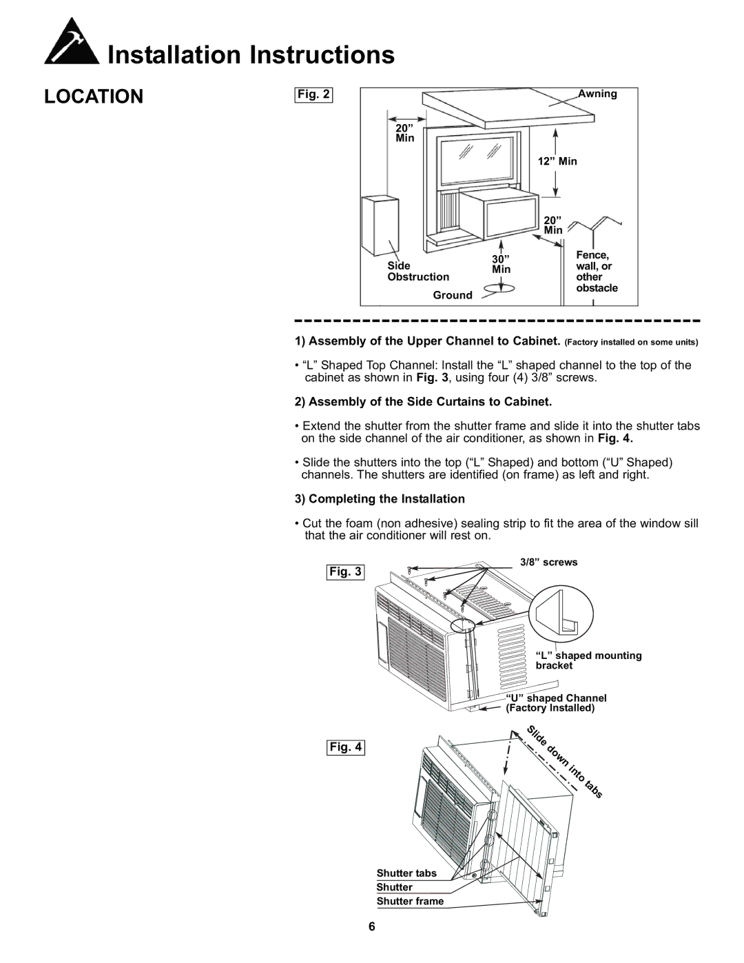
•“L” Shaped Top Channel: Install the “L” shaped channel to the top of the cabinet as shown in Fig. 3, using four (4) 3/8” screws.
2) Assembly of the Side Curtains to Cabinet.
•Extend the shutter from the shutter frame and slide it into the shutter tabs on the side channel of the air conditioner, as shown in Fig. 4.
•Slide the shutters into the top (“L” Shaped) and bottom (“U” Shaped) channels. The shutters are identified (on frame) as left and right.
3) Completing the Installation
•Cut the foam (non adhesive) sealing strip to fit the area of the window sill that the air conditioner will rest on.
Fig. 3
3/8” screws
“L” shaped mounting bracket
![]()
![]() “U” shaped Channel
“U” shaped Channel ![]()
![]()
![]()
![]() (Factory Installed)
(Factory Installed)
Fig. 4
Shutter tabs
Shutter
Shutter frame ![]()
6
