Installation Instructions - Intergrated Application
Tools You Will Need
WA R N I N G !
While performing the installations described in this section; gloves, safety glasses or goggles should be worn.
Safety Glasses | Gloves |
| Level |
|
| ||
|
|
| |
|
| Flashlight | |
|
|
| Carpenter’s |
|
| Measuring | Square |
Drill & Hole Saw set |
| ||
Tape |
| ||
Preparing the Enclosure
Electrical Requirements
The appliance must be con- nected to an individual and properly grounded electrical outlet, protected by a 15 or 20 ampere circuit breaker or time delay fuse.
IMPORTANT!
Door Swing
Do not include the door within the enclosure; leave it outside of the enclosure to prevent the door swing from being obstructed.
•It is recommended that you do not install the wine cooler into a corner (i.e. directly beside a wall). This is to allow the door to have a greater than 90° opening swing. A limited door swing will prevent the shelves from sliding out as intended, and may lead to damaging the door gasket.
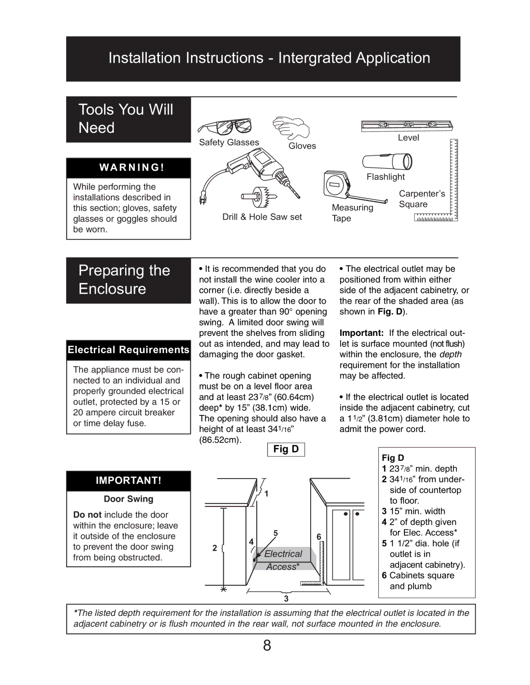
•The rough cabinet opening must be on a level floor area and at least 23 7/8” (60.64cm) deep* by 15” (38.1cm) wide.
The opening should also have a height of at least 341/16”
(86.52cm).
Fig D
} 1
|
| 4 | 5 | 6 |
|
|
| ||
2 | } |
|
| |
} | Electrical |
| ||
|
|
|
| |
|
|
| Access* |
|
|
|
| } |
|
|
|
| 3 |
|
•The electrical outlet may be positioned from within either side of the adjacent cabinetry, or the rear of the shaded area (as shown in Fig. D).
Important: If the electrical out- let is surface mounted (not flush) within the enclosure, the depth requirement for the installation may be affected.
•If the electrical outlet is located inside the adjacent cabinetry, cut a 11/2” (3.81cm) diameter hole to admit the power cord.
Fig D
123 7/8” min. depth
2 341/16” from under- side of countertop
to floor.
3 15” min. width
4 2” of depth given for Elec. Access*
5 1 1/2” dia. hole (if outlet is in adjacent cabinetry).
6 Cabinets square and plumb
*The listed depth requirement for the installation is assuming that the electrical outlet is located in the adjacent cabinetry or is flush mounted in the rear wall, not surface mounted in the enclosure.
8