Datel manual Technical Notes, Warnings Marking, DMS-PS-CM Series

Models: DMS-PS-CM

1 8
Download 8 pages 41.33 Kb
Page 3
Image 3
TECHNICAL NOTES

DMS-PS-CM Series

High Efficiency, AC/DC Instrumentation Power

Supplies with Individually Isolated Outputs


Ordering Information and Selection Guide


MPS Part No.


Rated Power


Efficiency


V1 Output


V2 Output


V3 Output


DMS-PS1-CM


5 Watts


75%


5Vdc/1A


DMS-PS2-CM


5 Watts


73%


5Vdc/0.65A


4.85Vdc/0.2A


—­


DMS-PS3-CM


5 Watts


71%


5Vdc/0.35A


4.85Vdc/0.2A


4.85Vdc/0.2A


DMS-PS4-CM


10 Watts


80%


24Vdc/0.45A


DMS-PS5-CM


10 Watts


75%


24Vdc/0.35A


4.85Vdc/0.2A


—­


DMS-PS6-CM


10 Watts


73%


24Vdc/0.30A


4.85Vdc/0.2A


4.85Vdc/0.2A


DMS-PS7-CM


16 Watts


82%


24Vdc/0.70A


DMS-PS8-CM


16 Watts


76%


24Vdc/0.60A


4.85Vdc/0.2A


—­


DMS-PS9-CM


16 Watts


74%


24Vdc/0.55A


4.85Vdc/0.2A


4.85Vdc/0.2A


DMS-PS10-CM


16 Watts


82%


12Vdc/1.35A


Efficiency typical @120V/60Hz

TECHNICAL NOTES

IMPORTANT! To ensure safe and reliable operation, DMS-PS-CM power supplies must be installed and serviced by qualified personnel. Contact Murata Power Solutions if there is any doubt regarding their installation and/or operation. Please read all of the following technical and application notes BEFORE installing or making connections to DMS-PS-CM power supplies.

Warnings (Marking)

Caution, unit may become hot in normal operation, thereby creat- ing a potential burn hazard. Disconnect ac mains and then allow unit to cool before servicing.

Reference document: IEC 417, No. 5041.

Dangerous, potentially lethal voltages are present during normal operation. Disconnect ac mains before servicing.

Reference document: IEC 417, No. 5036.

Caution, refer to accompanying documents for more informa- tion. Reference document: ISO 3864, No. B.3.1.

1.Shock Hazard: DMS-PS-CM Series power supplies feature touch-proof terminals blocks and fully-isolated plastic construction, thereby greatly reduc- ing the risk of electrical shock. However, these are mains-powered devices whose operation is derived from hazardous and potentially lethal voltages.

All service and installation must be performed by qualified personnel, with the ac supply voltage de-energized. Before making connections to any of the unit’s terminal blocks, use a digital voltmeter to verify that the ac supply is de-energized (off).

2.AC Supply Fuse (F1): All DMS-PS-CM Series power supplies are equipped with a built-in 1A/250V time-lag fuse. Replacement fuses must be of the same type and rating; please refer to the Functional Specifications section of this datasheet for more information. F1 is conservatively rated in order to reduce nuisance tripping which might occur during power-up or output overload conditions. However, F1 is primarily intended to provide protection in the event of catastrophic failure in the DMS-PS-CM’s ac/dc converter.

www.murata-ps.com

3.Fuse Replacement: If any dc-output drops to zero volts, and no fault conditions exist within the external load circuitry or the ac mains, F1 may have failed. F1 is located on the circuit (etch) side of the pc-board. Fuse replacement is performed by first de-energizing and then disconnecting the ac mains from TB4. Next, disconnect all load wiring from TB1, TB2, and TB3. Lastly, remove the four screws that secure the pc-board to the plastic case. After making sure that the new fuse is securely attached to its mounting clips, re-assemble the unit using all four screws. Reconnect all input and output wiring and re-apply ac power.

If the unit still does not operate properly, and the ac supply at TB4 is measured to be within its specified operating range, the power supply is defective and must be replaced. Except for F1, DMS-PS-CM supplies contain no other user-serviceable components.

4.Wire Gauges and Fusing: All wiring connected to the DMS-PS-CM’s terminal blocks must meet the requirements specified in the Functional Specifications section. All ac supply and load wiring must be rated for the voltages and currents they will conduct and must comply with any code or application-mandated requirements pertaining to the user’s specific installation. Applications subject to vibration should include adequate strain reliefs on both input and output wiring. Install the strain reliefs within 2-3 inches (5-7.5cm) of the terminal blocks.

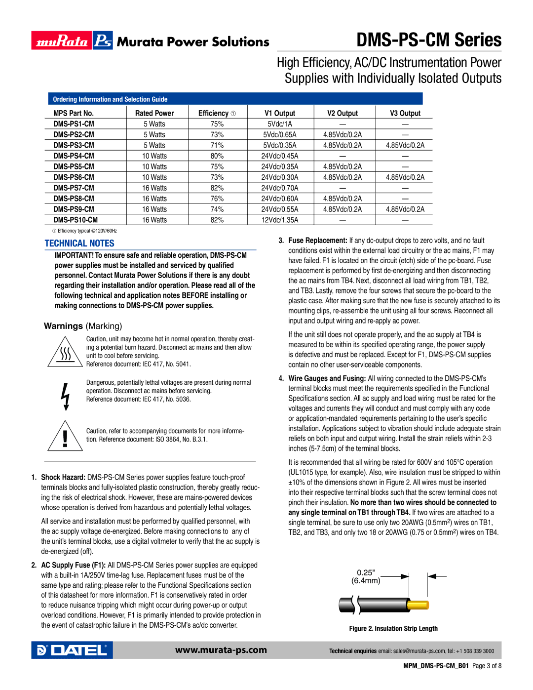
It is recommended that all wiring be rated for 600V and 105°C operation (UL1015 type, for example). Also, wire insulation must be stripped to within ±10% of the dimensions shown in Figure 2. All wires must be inserted into their respective terminal blocks such that the screw terminal does not pinch their insulation. No more than two wires should be connected to any single terminal on TB1 through TB4. If two wires are attached to a single terminal, be sure to use only two 20AWG (0.5mm2) wires on TB1, TB2, and TB3, and only two 18 or 20AWG (0.75 or 0.5mm2) wires on TB4.

0.25"

(6.4mm)

Figure 2. Insulation Strip Length

Technical enquiries email: sales@murata-ps.com, tel: +1 508 339 3000

MPM_DMS-PS-CM_B01Page 3 of 8

Page 3
Image 3
Datel manual Technical Notes, Warnings Marking, DMS-PS-CM Series, High Efficiency, AC/DC Instrumentation Power