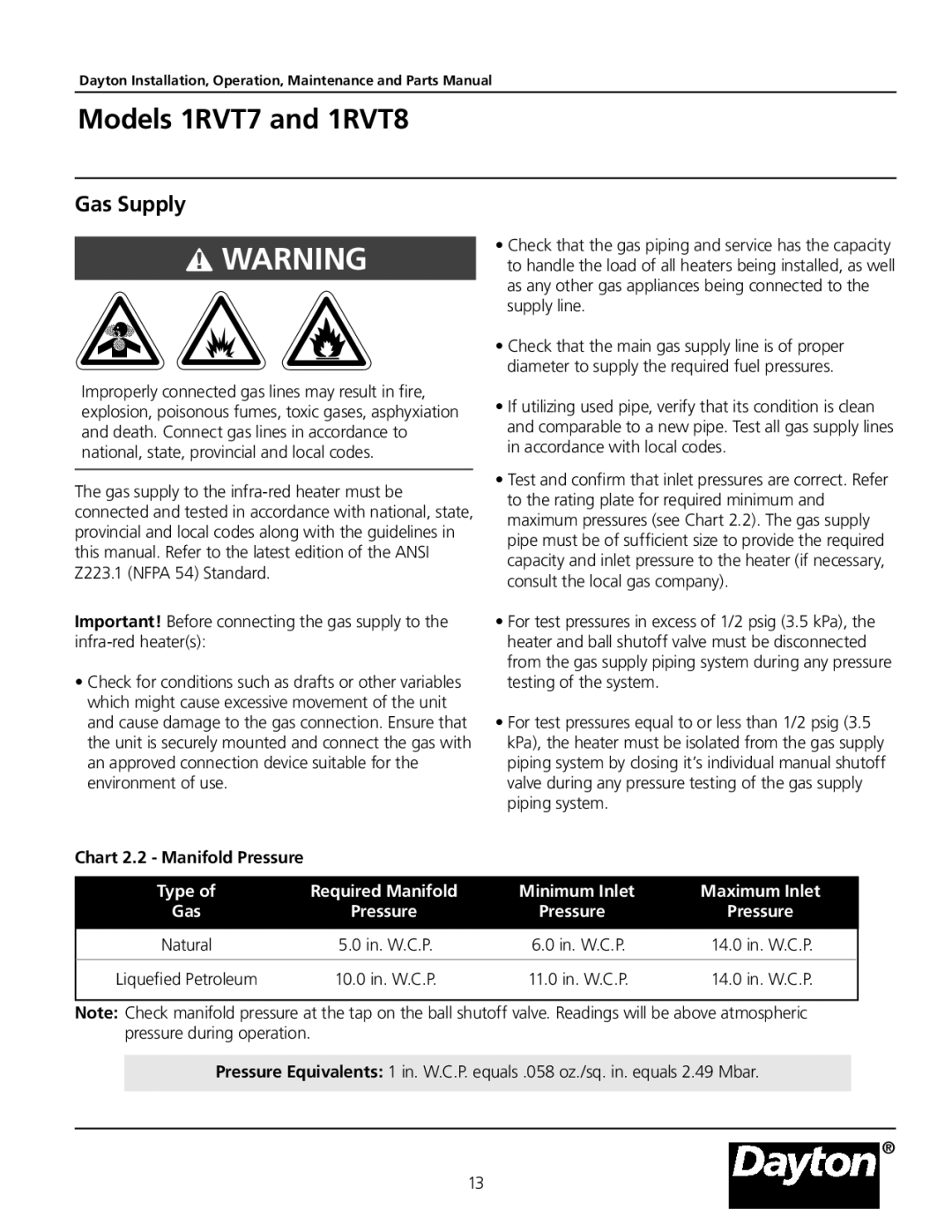
1RVT7, 1RVT8 specifications
Dayton 1RVT8 and 1RVT7 are innovative products designed for various applications while setting new standards in performance and efficiency. These models are primarily designed for HVAC and ventilation systems, providing reliable and cost-effective solutions for both commercial and residential settings.One of the distinguishing features of Dayton 1RVT8 and 1RVT7 is their energy efficiency. Both models are engineered to minimize energy consumption while delivering optimal airflow. This is achieved through advanced motor technology, which utilizes high-efficiency motors that not only reduce operational costs but also comply with stringent energy regulations. The units operate at low wattages, making them an environmentally friendly choice.
The design of these units emphasizes durability and reliability. Built with high-quality materials, they are constructed to withstand challenging conditions, ensuring a long service life. The robust design minimizes maintenance needs, allowing users to enjoy uninterrupted operation. This reliability is further enhanced by the inclusion of thermal protection, which safeguards the motors from overheating, thus prolonging their lifespan.
Dayton 1RVT8 and 1RVT7 also feature an array of user-friendly controls and settings. The intuitive control panel allows for easy adjustments, offering multiple speed options to cater to specific airflow requirements. This versatility ensures that users can optimize performance depending on their unique needs. Additionally, the units are compatible with various smart home systems, enabling automated control and integration into broader building management systems.
In terms of noise level, both models operate quietly, ensuring minimal disruption in their surroundings. This characteristic is particularly beneficial in environments where noise pollution needs to be reduced, such as offices, healthcare facilities, or residential spaces.
Another key characteristic of Dayton 1RVT8 and 1RVT7 is their compact design. The units are designed to fit in tight spaces, making them suitable for installation in areas where traditional equipment would be impractical. This space-saving feature is a significant advantage for many users looking to optimize their floor plans without sacrificing performance.
Overall, Dayton 1RVT8 and 1RVT7 represent a powerful combination of efficiency, durability, and versatility. They are well-suited for a variety of applications, making them a top choice for users seeking reliable, high-performance ventilation solutions. Whether for heating, cooling, or air circulation, these models deliver on the promise of quality and functionality.

