Dayton Installation, Operation, Maintenance and Parts Manual
Models 1RVT7 and 1RVT8
Chart 1.1 - Clearance to Combustibles in Inches (see Figure 1.1)
Model No. | Mounting | Sides | Back | Top | Below | End(s) | Front | |
Angle* | ||||||||
|
|
|
|
|
|
| ||
|
|
|
|
|
|
|
| |
1RVT7 | 0° | 14 | N/A | 13 | 46 | 22 | N/A | |
34,000 [Natural Gas] | 30° | N/A | 8 | 17 | 46 | 22 | 46 | |
|
|
|
|
|
|
|
| |
1RVT8 | 0° | 14 | N/A | 13 | 46 | 22 | N/A | |
34,000 [LP Gas] | 30° | N/A | 8 | 17 | 46 | 22 | 46 | |
|
|
|
|
|
|
|
|
* Heaters mounted on an angle between 0° to 30° must maintain clearances posted for 0° or 30°; whichever is greater.
Certain applications (awnings, fabrics, plastics, sprinklers, insulation) may require the heater to be mounted at a distance in excess of the published clearances to combustibles. Contact the factory.
Important! If the heater is mounted beneath a non- combustible surface an 8 in. minimum top clearance must be maintained from the top of the heater to prevent overheating the controls.
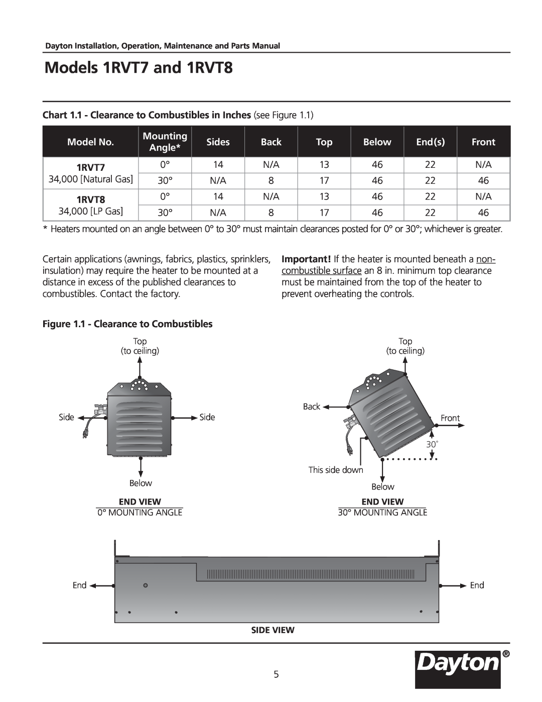
Figure 1.1 - Clearance to Combustibles
Top | Top |
(to ceiling) | (to ceiling) |
|
| Back |
Side | Side | Front |
|
| 30˚ |
|
| This side down |
| Below | Below |
|
| |
| END VIEW | END VIEW |
| 0° MOUNTING ANGLE | 30° MOUNTING ANGLE |
End | End |
SIDE VIEW
®
5