Dayton Operating Instructions and Parts Manual
Models 3E358B and 3E359B
Maintenance (Continued)
FUEL LINES
(Procedure for tightening fuel lines)
1.Remove upper shell (See Figure 8, page 7).
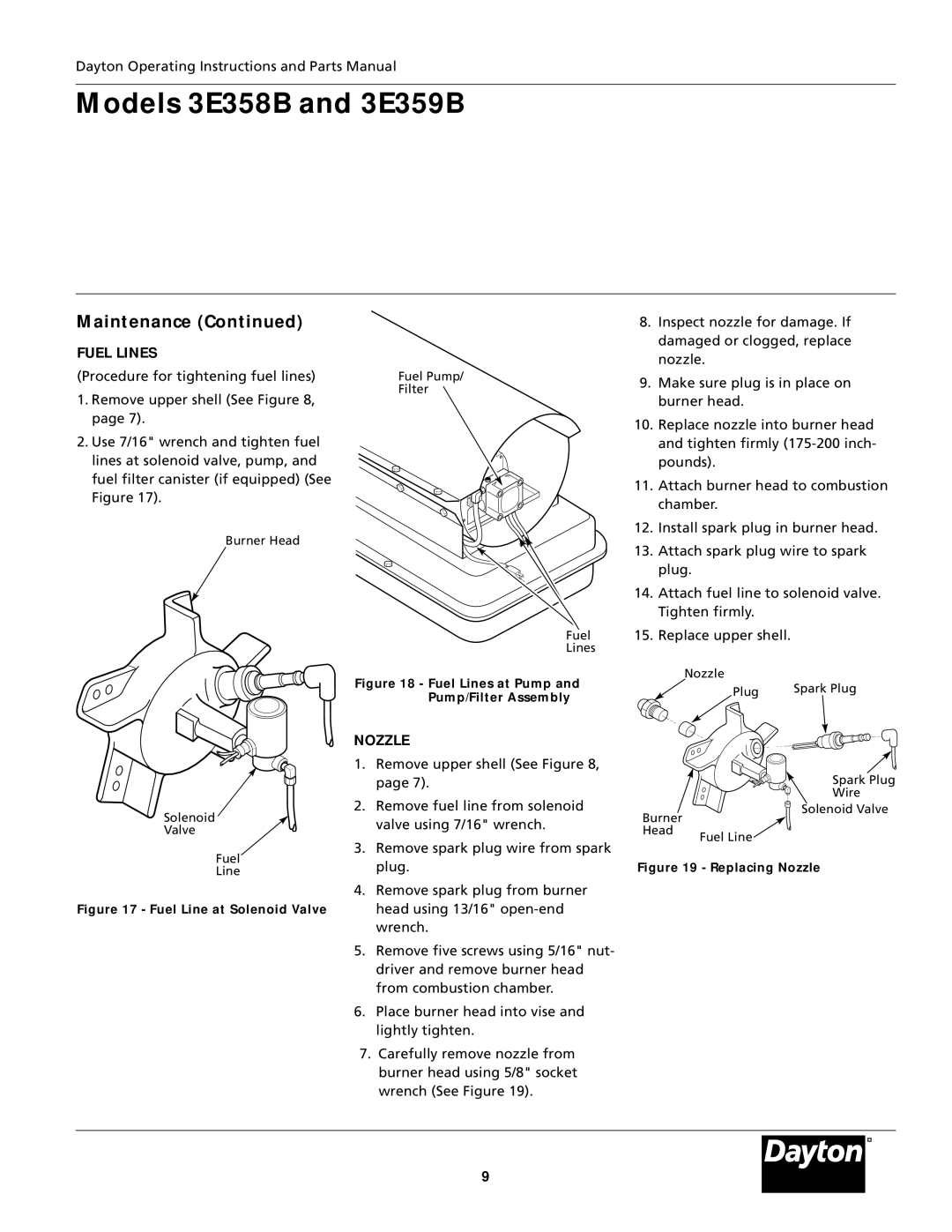
2.Use 7/16" wrench and tighten fuel lines at solenoid valve, pump, and fuel filter canister (if equipped) (See Figure 17).
Fuel Pump/ Filter
8.Inspect nozzle for damage. If damaged or clogged, replace nozzle.
9.Make sure plug is in place on burner head.
10.Replace nozzle into burner head and tighten firmly
11.Attach burner head to combustion chamber.
12.Install spark plug in burner head.
Burner Head
Solenoid
Valve
Fuel
Line
Figure 17 - Fuel Line at Solenoid Valve
13. Attach spark plug wire to spark plug.
14. Attach fuel line to solenoid valve. Tighten firmly.
Fuel 15. Replace upper shell.
Lines
Figure 18 - Fuel Lines at Pump and | Nozzle |
| |
Plug | Spark Plug | ||
Pump/Filter Assembly | |||
|
|
NOZZLE |
|
| |
1. | Remove upper shell (See Figure 8, |
|
|
| page 7). |
| Spark Plug |
2. | Remove fuel line from solenoid |
| Wire |
Burner | Solenoid Valve | ||
| valve using 7/16" wrench. |
| |
| Head | Fuel Line | |
|
| ||
3. | Remove spark plug wire from spark |
| |
|
| ||
| plug. | Figure 19 - Replacing Nozzle | |
4.Remove spark plug from burner head using 13/16"
5.Remove five screws using 5/16" nut- driver and remove burner head from combustion chamber.
6.Place burner head into vise and lightly tighten.
7.Carefully remove nozzle from burner head using 5/8" socket wrench (See Figure 19).
®
9