Dayton Operating Instructions and Parts Manual | 3VG79B |
Dayton® Portable
Forced Air Heater
Theory of Operation
THE FUEL SYSTEM
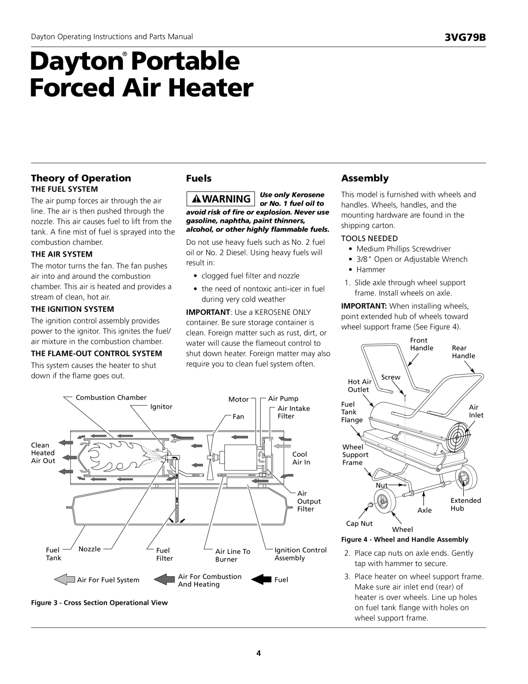
The air pump forces air through the air line. The air is then pushed through the nozzle. This air causes fuel to lift from the tank. A fine mist of fuel is sprayed into the combustion chamber.
THE AIR SYSTEM
The motor turns the fan. The fan pushes air into and around the combustion chamber. This air is heated and provides a stream of clean, hot air.
THE IGNITION SYSTEM
The ignition control assembly provides power to the ignitor. This ignites the fuel/ air mixture in the combustion chamber.
THE
This system causes the heater to shut down if the flame goes out.
Fuels
Use only Kerosene or No. 1 fuel oil to
avoid risk of fire or explosion. Never use gasoline, naphtha, paint thinners, alcohol, or other highly flammable fuels.
Do not use heavy fuels such as No. 2 fuel oil or No. 2 Diesel. Using heavy fuels will result in:
•clogged fuel filter and nozzle
•the need of nontoxic
IMPORTANT: Use a KEROSENE ONLY container. Be sure storage container is clean. Foreign matter such as rust, dirt, or water will cause the flameout control to shut down heater. Foreign matter may also require you to clean fuel system often.
Assembly
This model is furnished with wheels and handles. Wheels, handles, and the mounting hardware are found in the shipping carton.
TOOLS NEEDED
•Medium Phillips Screwdriver
•3/8" Open or Adjustable Wrench
•Hammer
1.Slide axle through wheel support frame. Install wheels on axle.
IMPORTANT: When installing wheels, point extended hub of wheels toward wheel support frame (See Figure 4).
| Front |
|
| Handle | Rear |
|
| Handle |
Hot Air | Screw |
|
|
| |
Outlet |
|
|
Combustion Chamber | Motor | Air Pump |
| Ignitor | Air Intake |
| Fan | Filter |
Clean |
|
|
Heated |
| Cool |
Air Out |
| Air In |
|
| Air |
|
| Output |
|
| Filter |
Fuel | Nozzle | Fuel | Air Line To | Ignition Control |
Tank |
| Filter | Burner | Assembly |
| Air For Fuel System |
| Air For Combustion | Fuel |
|
| And Heating | ||
|
|
|
|
Figure 3 - Cross Section Operational View
Fuel | Air | |
Tank | ||
Inlet | ||
Flange | ||
|
Wheel
Support
Frame
Nut![]()
![]()
Extended
Axle Hub
Cap Nut
Wheel
Figure 4 - Wheel and Handle Assembly
2.Place cap nuts on axle ends. Gently tap with hammer to secure.
3.Place heater on wheel support frame. Make sure air inlet end (rear) of heater is over wheels. Line up holes on fuel tank flange with holes on wheel support frame.
4