
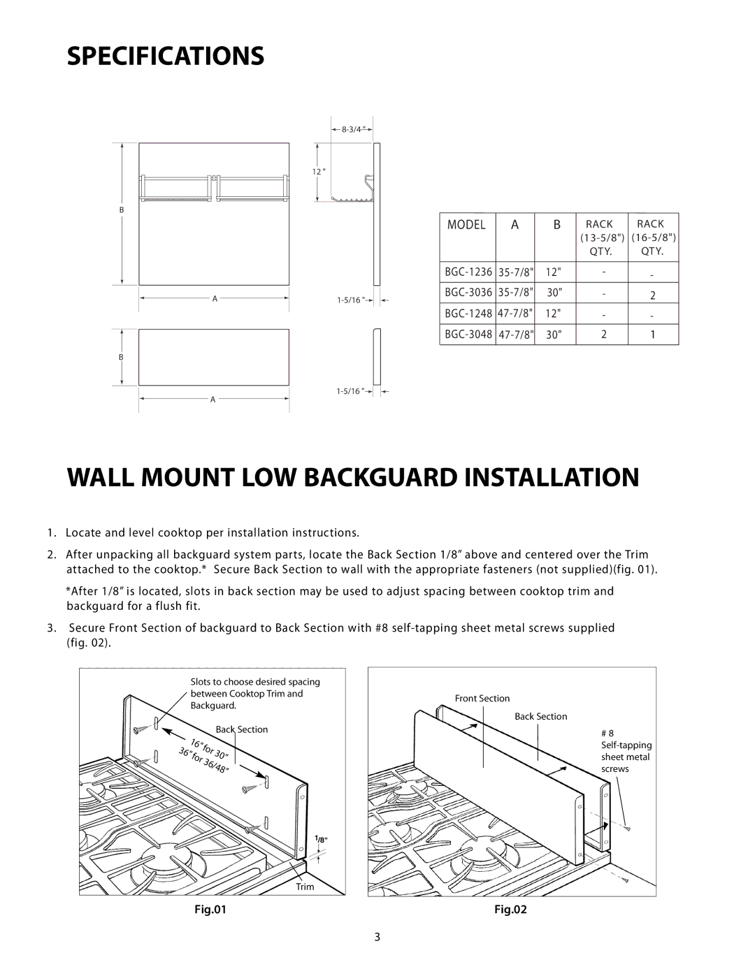
BGC-1248, BGC-3036, BGC-1236, BGC-3048 specifications
The DCS BGC series, including models BGC-3048, BGC-1236, BGC-3036, and BGC-1248, represents a significant advancement in the field of battery gas control systems. Each model is designed to enhance safety, efficiency, and reliability in various industrial applications, especially in environments where battery maintenance and monitoring are critical.The BGC-3048 model is a highly sophisticated system equipped with advanced algorithms that monitor the charging and discharging processes of batteries. One of its main features is its ability to provide real-time data analysis, which helps in predicting battery life and optimizing usage. The BGC-3048 includes a user-friendly interface that simplifies navigation through various operational parameters. Additionally, its compatibility with multiple battery types makes it a versatile choice for different applications.
In contrast, the BGC-1236 model focuses primarily on compact design without sacrificing performance. It is tailored for smaller setups where space is a constraint but still requires high reliability. This model features a robust data logging capability, enabling users to track battery performance over time. Its ease of integration with existing systems means that companies can upgrade their battery management without extensive overhauls.
The BGC-3036 model is known for its high-capacity handling and is ideally suited for larger battery systems. It utilizes state-of-the-art sensing technology to provide precise measurements, which helps in assessing battery health accurately. The user interface is designed for intuitive operation, allowing operators to quickly adapt to the system. Furthermore, its remote monitoring capabilities enable maintenance teams to troubleshoot issues from afar, significantly reducing downtime.
Lastly, the BGC-1248 model epitomizes versatility and scalability. It can manage multiple battery configurations simultaneously, making it an excellent choice for facilities with a diverse range of batteries. This model is equipped with intelligent software that learns from usage patterns, improving its predictive analytics over time. With features like alarm systems for potential issues and energy consumption monitoring, the BGC-1248 not only ensures safety but also enhances overall operational efficiency.
In summary, the DCS BGC-3048, BGC-1236, BGC-3036, and BGC-1248 models are engineered to meet the varying needs of battery gas control. With their innovative technologies, user-friendly interfaces, and robust capabilities, these systems are at the forefront of battery management solutions, ensuring that businesses can operate with confidence and efficiency.