INSTALLATION

Do not locate either the gas or electrical supply line directly over the top of the heater, due to the extreme heat that may cause overheating or damage. The heater must be installed in a location that is accessible for service. The heater must be installed in a way that doesn’t restrict fresh airflow to the unit. The heater cannot be installed in a recessed area. Doing so may cause poor performance and heat damage to the surrounding area.

MOUNTING

Each heater must be installed so that the minimum clearance to combustibles are maintained. Combustible materials are defined as wood, paper, foliage, plastic, plexiglass or other materials capable of being ignited and burned. Such materials shall be considered combustible even though flame-proofed, fire retardant treated or plastered. Additional clearances may be required for glass, painted surfaces and other materials which may be damaged by radiant or convection heat.

ELECTRICAL

Important!

A 24 VAC, 40 VA transformer has been included with the product. It is imperative to use this transformer.

The on-off control of the heater should be controlled from 120 VAC side of the transformer (see wiring diagram). A UL approved outdoor wall switch must be used for this purpose. The transformer must be mounted a minimum of 12” from the heater in a weather protected cover. Do not put the transformer in the heater or above the heater (this will damage the unit.) A step down transformer approved as having at least a 40 VA rating must be utilized for each connected heater. Control wires used to electrically connect one or more heaters together must have both adequate capacity and insulation temperature ratings for the total connected load. Use at least 18 ga. wire up to 50 ft. from heater to transformer or wall switch. Use 16 ga. over 50 ft. distance. If the original wires supplied should need replacement, they must be replaced with wiring material having a temperature rating of at least 105 degrees Centigrade/221º Fahrenheit.

GAS PIPING

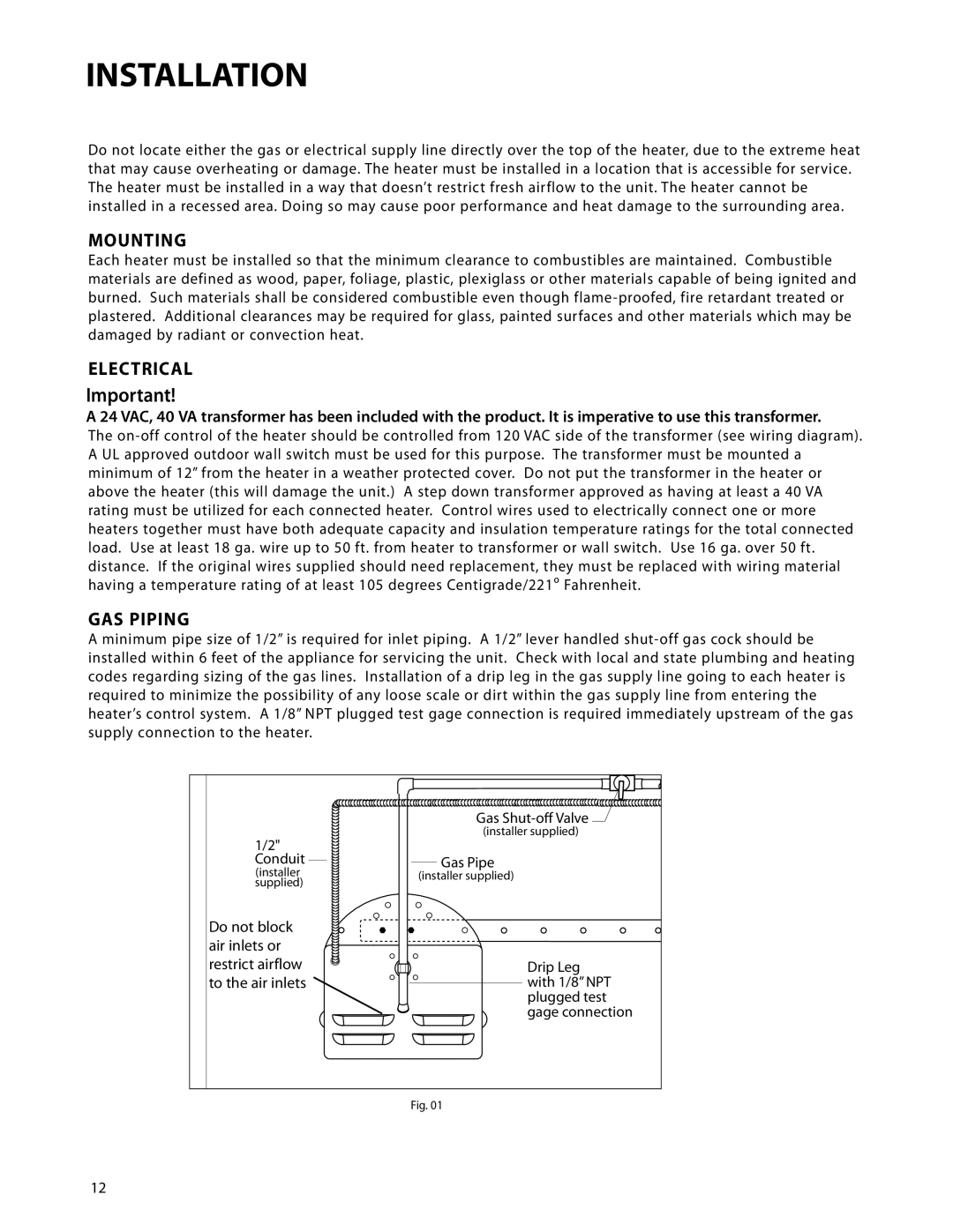
A minimum pipe size of 1/2” is required for inlet piping. A 1/2” lever handled shut-off gas cock should be installed within 6 feet of the appliance for servicing the unit. Check with local and state plumbing and heating codes regarding sizing of the gas lines. Installation of a drip leg in the gas supply line going to each heater is required to minimize the possibility of any loose scale or dirt within the gas supply line from entering the heater’s control system. A 1/8” NPT plugged test gage connection is required immediately upstream of the gas supply connection to the heater.

1/2" Conduit

(installer

supplied)

Do not block air inlets or restrict airflow to the air inlets

Gas Shut-o! Valve

(installer supplied)

Gas Pipe

(installer supplied)

Drip Leg with 1/8” NPT plugged test gage connection

Fig. 01

12

Page 14
Image 14
DCS DRH-48N manual Mounting, Electrical, GAS Piping

DRH-48N specifications

The DCS DRH-48N is a state-of-the-art drone designed for reconnaissance and surveillance missions, boasting advanced features and remarkable capabilities suited for a multitude of applications. This drone exemplifies the next generation of unmanned aerial vehicles, integrating cutting-edge technology for both civilian and military use.

One of the most striking characteristics of the DRH-48N is its impressive flight endurance. With the ability to remain airborne for extended periods, this drone can cover vast areas without the need for frequent recharging or refueling. This makes it ideal for operations that require prolonged monitoring, such as border security, disaster management, and agricultural assessments.

The DRH-48N is equipped with a high-resolution imaging system that leverages both optical and infrared sensors. This dual-sensor setup allows operators to capture detailed images and videos in a variety of lighting conditions, including complete darkness. The real-time data transmission capabilities enable remote analysts to receive live feeds, facilitating quicker decision-making in critical situations.

Moreover, the drone features a robust autopilot system that supports advanced flight modes including waypoint navigation, automated takeoff, and landing capabilities. This technology reduces pilot workload and increases mission efficiency, allowing even novice operators to utilize the drone effectively.

Durability is another highlight of the DRH-48N, constructed from lightweight yet resilient materials. This ensures not only longevity but also resistance to harsh weather conditions, enabling the drone to operate in diverse environments. Additionally, the modular design simplifies maintenance, allowing for quick replacements of components or upgrades to the system.

Furthermore, DCS has integrated sophisticated communication technologies within the DRH-48N. This includes secure data links that protect mission-critical information from interception, ensuring that sensitive operations maintain a high level of confidentiality.

In summary, the DCS DRH-48N stands at the forefront of UAV technology, combining advanced imaging systems, superior flight endurance, robust autopilot features, and durable construction. These characteristics make it an invaluable asset in various sectors, paving the way for enhanced operational capabilities and efficiency in reconnaissance and surveillance missions across the globe.