5524, 5548P, 5524P, 5548 specifications
The Dell Networking series includes the switches Dell 5524P, 5548, 5548P, and 5524, designed to cater to a variety of networking needs in enterprise environments. These models are renowned for their robustness, scalability, and ease of deployment, making them suitable for both small and large-scale networks.The Dell 5524P switch is particularly notable for its Power over Ethernet (PoE) capabilities, supporting up to 24 ports. This feature allows the switch to deliver both data and power over the same cable, simplifying deployments for powered devices like IP cameras, VoIP phones, and wireless access points. With a switching capacity of 48 Gbps, the 5524P ensures efficient data handling, reducing latency and enhancing overall network performance.
On the other hand, the Dell 5548 switch is designed with a focus on scalability and advanced Layer 2 and Layer 3 functionality. It includes 48 Gigabit Ethernet ports and provides a switching capacity of 96 Gbps. The 5548 switch supports stacking technology, which simplifies management and allows multiple switches to act as a single unit. This is ideal for growing networks needing additional capacity without overhauling existing infrastructure.
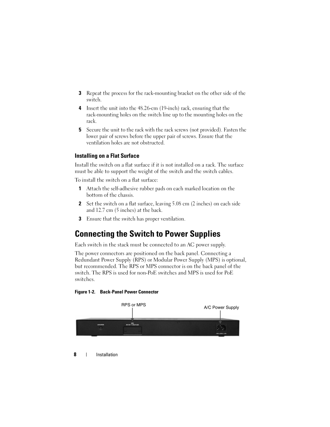
The Dell 5548P model builds upon the robust features of the 5548 while integrating PoE+ support, which provides up to 30 watts per port. This is optimal for high-power devices and enhances the overall flexibility of network deployments. The switch also incorporates advanced security features, enabling organizations to create secure network segments and enforce access controls.
Lastly, the Dell 5524 switch provides essential features suitable for smaller networks or as part of a larger network infrastructure. It offers 24 ports with a straightforward configuration, making it a cost-effective solution without compromising on performance. Its energy-efficient design is in line with modern environmental standards, reducing power consumption without sacrificing functionality.
In summary, the Dell 5524P, 5548, 5548P, and 5524 switches present a comprehensive range of features, suitable for diverse networking needs. With advanced technologies like PoE, stacking capability, and robust security, they cater to the requirements of busy enterprise environments, helping simplify management and enhance productivity while supporting future growth.