INSTALLATION
Front panel | Side panel |
3 | SOURCE | 1 |
| MENU | 2 |
| CH+ |
|
| 1 | 3 |
| CH- |
|
| 2 |
|
| VOL+ | 4 |
|
| |
| VOL- |
|
| STANDBY | 5 |
30 30
VIDEO
L
R
AV2
VIDEO
L
R
6
7
8
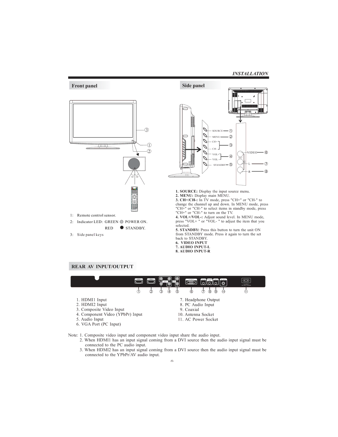
1:Remote control sensor.
2:Indicator LED: GREEN ![]() POWER ON.
POWER ON.
RED  STANDBY.
3:Side panel keys
1.SOURCE: Display the input source menu.
2.MENU: Display main MENU.
3.
4.
5.STANDBY: Press this button to turn the unit ON from STANDBY mode. Press it again to turn the set back to STANDBY.
6.VIDEO INPUT
7.AUDIO
8.AUDIO
REAR AV INPUT/OUTPUT
HDMI 1 | HDMI 2 |
Pr COMPONENT Pb
INPUT
AV1Y
| VGA INPUT | HEADPHONE PC AUDIO COAXIAL | RF INPUT | ||||||
AUDIO L |
| INPUT |
|
|
| ||||
INPUT |
|
|
|
|
|
|
| ||
|
|
|
|
|
|
|
| AC INPUT | |
R |
|
|
|
|
|
| |||
|
|
|
|
|
|
|
|
|
|
| 1 | 2 | 3 | 4 | 5 | 6 | 7 | 8 | 9 | 10 | 11 |
1. | HDMI1 Input |
|
|
| 7. | Headphone Output |
|
| |||
2. | HDMI2 Input |
|
|
| 8. | PC Audio Input |
|
|
| ||
3. | Composite Video Input |
|
|
| 9. | Coaxial |
|
|
|
|
|
4. | Component Video (YPbPr) Input |
|
|
| 10. | Antenna Socket |
|
|
| ||
5. Audio Input |
|
|
| 11. AC Power Socket |
|
| |||||
6. VGA Port (PC Input) |
|
|
|
|
|
|
|
|
|
| |
Note: 1. Composite video input and component video input share the audio input.
2.When HDMI1 has an input signal coming from a DVI source then the audio input signal must be connected to the PC audio input.
3.When HDMI2 has an input signal coming from a DVI source then the audio input signal must be connected to the YPbPr/AV audio input.