Rev 1.0
Overview
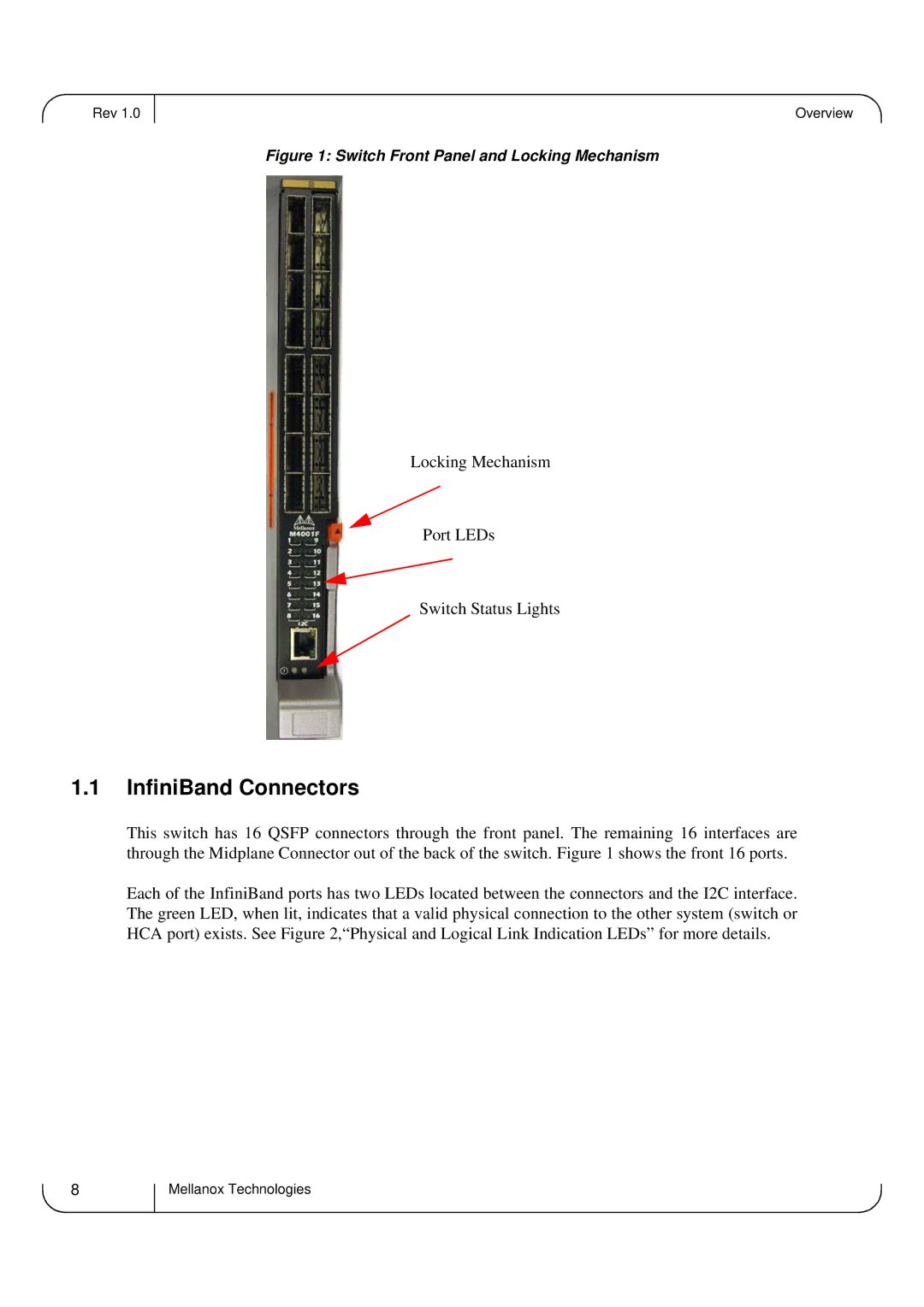
Figure 1: Switch Front Panel and Locking Mechanism
Locking Mechanism
Port LEDs
Switch Status Lights
1.1InfiniBand Connectors
This switch has 16 QSFP connectors through the front panel. The remaining 16 interfaces are through the Midplane Connector out of the back of the switch. Figure 1 shows the front 16 ports.
Each of the InfiniBand ports has two LEDs located between the connectors and the I2C interface. The green LED, when lit, indicates that a valid physical connection to the other system (switch or HCA port) exists. See Figure 2,“Physical and Logical Link Indication LEDs” for more details.
8
Mellanox Technologies