
T310 specifications
The Dell PowerEdge T310 is a tower server designed to meet the needs of small businesses and remote offices looking for an efficient and reliable server solution. With its robust architecture and user-friendly features, the T310 provides a solid foundation for various applications, such as file sharing, data backup, and running virtual machines.One of the standout features of the Dell T310 is its powerful processing capabilities. It is equipped with Intel Xeon processors, which deliver impressive performance and reliability. These processors are designed for multi-threaded applications and can handle intensive workloads, making the T310 suitable for demanding environments. The server supports up to two Intel Xeon processors, allowing businesses to scale their computing power as their needs grow.
Memory capacity is another key characteristic of the T310. It supports up to 32GB of DDR3 RAM, which is essential for running multiple applications simultaneously without any performance degradation. The memory can be expanded easily, allowing businesses to increase capacity as their data needs evolve.
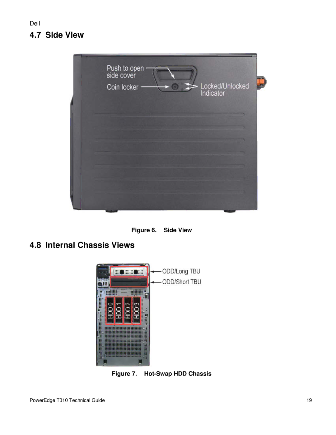
Storage options on the T310 are flexible and extensive. The server features up to four hot-swappable 3.5-inch hard drive bays, supporting SATA and SAS drives. This allows for a maximum internal storage capacity of up to 8TB, giving businesses the space they need for data-intensive tasks. The hot-swappable design enhances uptime, enabling users to replace drives without shutting down the server.
In terms of connectivity, the Dell T310 is equipped with multiple USB ports, Ethernet ports, and optional expansion slots. It also supports various RAID configurations, ensuring data protection and redundancy. This flexibility makes it an excellent choice for organizations looking to maintain data integrity while maximizing performance.
Another notable aspect of the T310 is its energy efficiency. The server incorporates Dell’s energy-efficient technologies, helping businesses reduce their overall energy consumption and lower operational costs. The compact design of the T310 allows it to fit easily into standard office environments without taking up excessive space.
Overall, the Dell PowerEdge T310 stands out as a reliable and versatile tower server. Its combination of processing power, memory capacity, flexible storage options, and energy-efficient technologies make it a great choice for small to medium-sized businesses looking for a dependable server solution to support their critical applications and services.