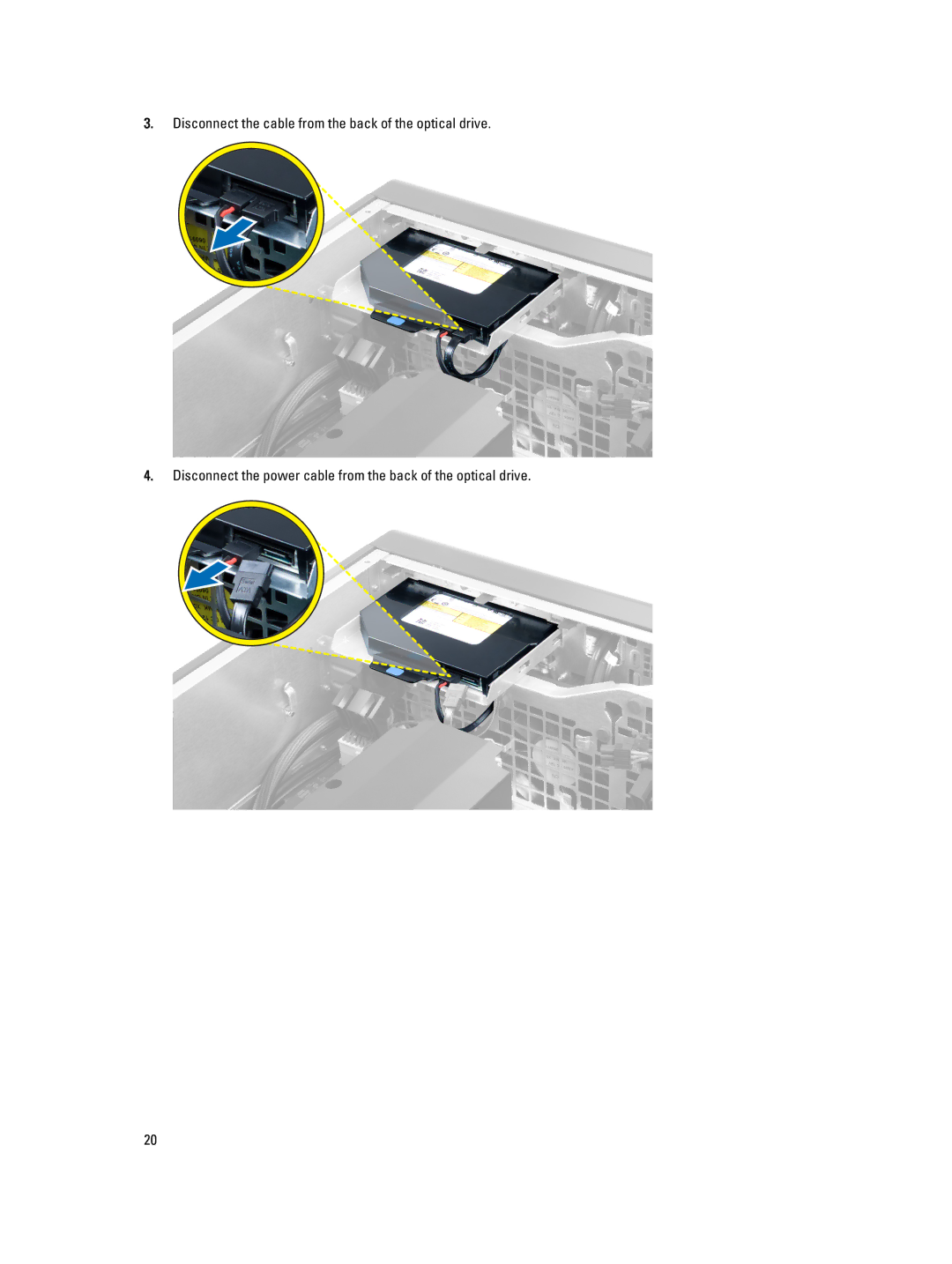
Manuals
/
Dell
/
Computer Equipment
/
Server
Dell
T7610 owner manual Disconnect the cable from the back of the optical drive
Models:
T7610
1
20
81
81
Download
81 pages
45.18 Kb
17
18
19
20
21
22
23
24
<
>
Troubleshooting
Specifications
Install
Error codes
Dell Reliable Memory Technology RMT has discovered and isolated errors in system memory. You may continue to work. Memory module replacement is recommended. Please refer to the RMT Event log screen in BIOS setup for specific DIMM information
System Configuration
solid amber light - the computer does not start, indicating a problem
Diagnostics
System Setup
Follow the procedures in Before Working Inside Your Computer
Page 20
Image 20
3.
Disconnect the cable from the back of the optical drive.
4.
Disconnect the power cable from the back of the optical drive.
20
Page 19
Page 21
Page 20
Image 20
Page 19
Page 21
Contents
Dell Precision Workstation T7610 Owners Manual
Regulatory Model D02X Regulatory Type D02X002
Notes, Cautions, and Warnings
1 Working on Your Computer
Contents
2 Removing and Installing Components
4 System Setup
5 Diagnostics
6 Troubleshooting Your Computer
3 Additional Information
Technical Specifications
Contacting Dell
Page
Working on Your Computer
Before Working Inside Your Computer
Turning Off Your Computer
After Working Inside Your Computer
Page
Page
System Overview
Removing and Installing Components
Recommended Tools
Removing the Power Supply Unit PSU
Installing the Power Supply Unit PSU
1. Follow the procedures in Before Working Inside Your Computer
2. Follow the procedures in After Working Inside Your Computer
Installing the Front Cover
3. Follow the procedures in After Working Inside Your Computer
Removing the Front Cover
1. Follow the procedures in Before Working Inside Your Computer
Removing the Hard Drive
1. Follow the procedures in Before Working Inside Your Computer
2. Remove the front cover
3. Pull the clasp of the hard-drive bracket in an outward direction
7. Flex the hard-drive bracket on both sides to loosen the hard drive
Installing the Hard Drive
5. Follow the procedures in After Working Inside Your Computer
Installing the Left Cover
Removing the Left Cover
1. Follow the procedures in Before Working Inside Your Computer
3. Follow the procedures in After Working Inside Your Computer
Removing the Intrusion Switch
Installing the Intrusion Switch
4. Follow the procedures in After Working Inside Your Computer
Removing the PCI Card
Installing the PCI Card
Removing the Slimline Optical Drive
4. Follow the procedures in After Working Inside Your Computer
1. Follow the procedures in Before Working Inside Your Computer
4. Disconnect the power cable from the back of the optical drive
3. Disconnect the cable from the back of the optical drive
Page
Installing the Slimline Optical Drive
Removing the Air Tunnel
4. Follow the procedures in After Working Inside Your Computer
1. Follow the procedures in Before Working Inside Your Computer
Installing the Air Tunnel
4. Follow the procedures in After Working Inside Your Computer
Installing the Memory
Removing the Coin-Cell Battery
Removing the Memory
1. Follow the procedures in Before Working Inside Your Computer
Installing the Coin-Cell Battery
Removing the Heatsink
4. Follow the procedures in After Working Inside Your Computer
1. Follow the procedures in Before Working Inside Your Computer
Installing the Heatsink
Removing the Heat-Sink Fan
5. Follow the procedures in After Working Inside Your Computer
1. Follow the procedures in Before Working Inside Your Computer
Installing the Heatsink Fan
Removing the System Fan
4. Follow the procedures in After Working Inside Your Computer
1. Follow the procedures in Before Working Inside Your Computer
6. Remove the graphics-card cable from the latch
Page
10. Disconnect the system-fan cable connectors from the system board
Installing the System Fan
10. Follow the procedures in After Working Inside Your Computer
Removing the I/O Panel and the USB 3.0 Ports
1. Follow the procedures in Before Working Inside Your Computer
3. Disconnect all the cables from the I/O panel
Installing the I/O Panel and the USB 3.0 Ports
1. Follow the procedures in Before Working On Your Computer
Removing the Power Switch
7. Follow the procedures in After Working Inside Your Computer
Installing the Power Switch
Removing the Speaker
5. Follow the procedures in After Working Inside Your Computer
1. Follow the procedures in Before Working Inside Your Computer
Installing the Speaker
4. Follow the procedures in After Working Inside Your Computer
2. Remove the screws that secure the right cover to the chassis
Removing the Right Cover
1. Follow the procedures in Before Working Inside Your Computer
Installing the Right Cover
Removing the 5.25-inch Optical Drive
3. Follow the procedures in After Working Inside Your Computer
1. Follow the procedures in Before Working Inside Your Computer
Installing the 5.25-inch Optical Drive
Removing the Thermal Sensor
5. Follow the procedures in After Working Inside Your Computer
1. Follow the procedures in Before Working Inside Your Computer
b. Unroute the thermal-sensor cable through the chassis clips
3. Perform the following steps
a. Disconnect the thermal-sensor cable from the system board
Installing the Thermal Sensor
Removing the Processor
5. Follow the procedures in After Working Inside Your Computer
1. Follow the procedures in Before Working Inside Your Computer
Installing the Processor
6. Follow the procedures in After Working Inside Your Computer
Removing the Hard-Drive Fan
1. Follow the procedures in Before Working Inside Your Computer
2. Remove a. left cover b. right cover c. PCI card
Installing the Hard-Drive Fan
Removing the Power Supply Unit PSU Card
4. Follow the procedures in After Working Inside Your Computer
1. Follow the procedures in Before Working Inside Your Computer
Installing the Power Supply Unit PSU Card
1. Install the screws that secure the PSU card to the chassis
2. Connect all the cables to the PSU card 3. Install the right cover
4. Follow the procedures in After Working Inside Your Computer
Removing the System Board
1. Follow the procedures in Before Working Inside Your Computer
h. chassis intrusion switch i. coin-cell battery j. PCI card
3. Disconnect all the connectors from the system board
Installing the System Board
3. Connect the connectors to the system board
4. Remove the screws that secure the system board to the chassis
2. Tighten the screws that secure the system board to the chassis
System Board Components
5. Follow the procedures in After Working Inside Your Computer
intrusion-switch connector
Page
Front Panel Chassis Lock
Additional Information
Memory Module Guidelines
Power Supply Unit PSU Lock
Navigation Keys
System Setup
Boot Sequence
System Setup Options
Table 3. System Configuration
NOTE If the hard drives are connected to a RAID controller card
Table 4. Video
Table 5. Security
Table 6. Secure Boot
Table 7. Performance
Default Setting Enable Hardware Prefetch
Default Setting Enable Dell Reliable Memory
Table 9. POST Behavior
Table 10. Virtualization Support
Updating the BIOS
System and Setup Password
Assigning a System Password and Setup Password
Deleting or Changing an Existing System and/or Setup Password
Disabling a System Password
11. Follow the procedures in After Working Inside Your Computer
1. Follow the procedures in Before Working Inside Your Computer
Page
Diagnostics
Enhanced Pre-Boot System Assessment ePSA Diagnostics
Page
Troubleshooting Your Computer
Diagnostic LEDs
A possible graphics card failure has occurred
Error Messages
Errors That Halt Your Computer Completely
Errors That Do Not Halt Your Computer
Errors That Soft Halt Your Computer
Table 15. Errors that do not halt your computer
Table 16. - Errors that soft halt your computer
Dell Reliable Memory Technology RMT has discovered and isolated errors in system memory. You may continue to work. Memory module replacement is recommended. Please refer to the RMT Event log screen in BIOS setup for specific DIMM information
Page
Technical Specifications
Table 17. Processor
Table 18. System Information
Table 19. Memory
Table 20. Video
Table 21. Audio
Table 22. Network
Table 23. Expansion Interfaces
supports one 5.25-inches SATA device or supports one
Table 25. External Connectors
Table 24. Drives
Table 26. Internal Connectors
two 164-pin connectors four when optional second processor is
solid amber light - the computer does not start, indicating a problem
blinking amber light - indicates a problem has occurred with the
Front USB Internal USB Front panel control
Table 27. Controls and Lights
amber/blinking light - see the service manual for specific diagnostic
Table 28. Power
4015.3 BTU/Hr at 100 VAC
4365.5 BTU/Hr at 107 VAC
105 G +/- 5% with pulse duration of 2 msec +/- 10% equivalent to
Table 30. Environmental
40 G +/- 5% with pulse duration of 2 msec +/- 10% equivalent to
Page
Contacting Dell
1. Visit dell.com/support