|
|
| WIRING DIAGRAM |
| |||||
S1 | F1 |
|
| EC | F2 | ||||
|
|
|
|
|
|
| |||
|
|
|
|
|
|
|
|
|
|
|
|
|
|
|
|
|
|
|
|
|
|
|
|
|
|
|
|
|
|
P1 | 1 | N/7 | P1 | 1 | MS1 |
P2 | 2 | L/8 | P2 | 2 |
|
|
|
|
|
MS ![]()
|
|
|
| LF1 |
|
| LF | AS |
|
|
|
| A1 | |
|
|
| CF | |
|
|
| V1 | |
A |
|
|
| |
| V |
|
| |
|
|
|
| |
|
| TL2 | TL3 | TL4 |
|
| TL1 | ||
|
|
|
| |
|
|
| T | PA1 |
| PA |
|
| |
|
|
|
|
M
LN
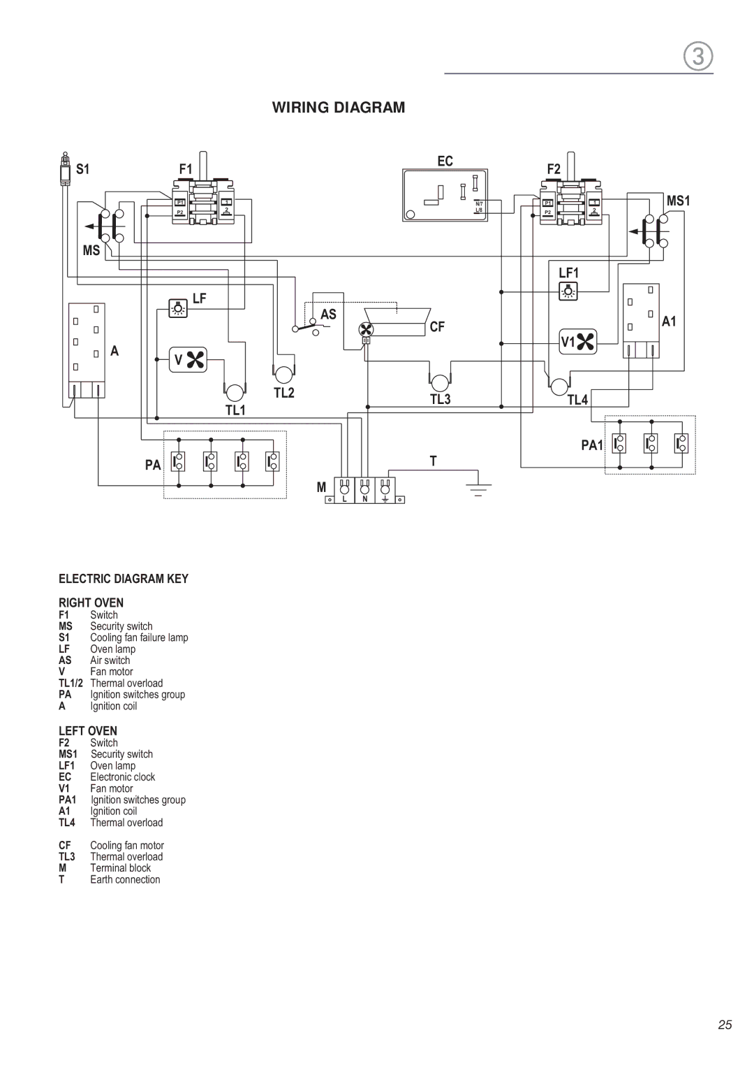
ELECTRIC DIAGRAM KEY
RIGHT OVEN
F1 | Switch |
MS | Security switch |
S1 | Cooling fan failure lamp |
v LF | en lamp |
AS | ir switch |
VFan motor
TL1/2 | Thermal overload |
gnPA | ition switches group |
gn A | ition coil |
LEFT OVEN
F2 | Switch |
MS1 | Security switch |
LF1v | en lamp |
leEC | ctronic clock |
V1 | Fan motor |
PA1Ign | ition switches group |
gnA1 | ition coil |
TL4 | Thermal overload |
CF Cooling fan motor
TL3 Thermal overload
MTerminal block
T Earth connection
25
