SPINDLE SPEEDS
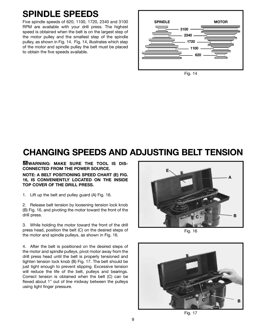
Five spindle speeds of 620, 1100, 1720, 2340 and 3100 RPM are available with your drill press. The highest speed is obtained when the belt is on the largest step of the motor pulley and the smallest step of the spindle pulley, as shown in Fig. 14. Fig. 14, illustrates which step of the motor and spindle pulley the belt must be placed to obtain the five speeds available.
SPINDLEMOTOR
3100
2340
1720
1100
620
Fig. 14
CHANGING SPEEDS AND ADJUSTING BELT TENSION
![]() WARNING: MAKE SURE THE TOOL IS DIS- CONNECTED FROM THE POWER SOURCE.
WARNING: MAKE SURE THE TOOL IS DIS- CONNECTED FROM THE POWER SOURCE.
NOTE: A BELT POSITIONING SPEED CHART (E) FIG. 16, IS CONVENIENTLY LOCATED ON THE INSIDE TOP COVER OF THE DRILL PRESS.
1.Lift up the belt and pulley guard (A) Fig. 16.
2.Release belt tension by loosening tension lock knob
(B) Fig. 16, and pivoting the motor toward the front of the drill press.
3.While holding the motor toward the front of the drill press head, position the belt (C) on the desired steps of the motor and spindle pulleys, as shown in Fig. 16.
4.After the belt is positioned on the desired steps of the motor and spindle pulleys, pivot motor away from the drill press head until the belt is properly tensioned and tighten tension lock knob (B) Fig. 17. The belt should be just tight enough to prevent slipping. Excessive tension will reduce the life of the belt, pulleys and bearings. Correct tension is obtained when the belt (C) can be flexed about 1" out of line midway between the pulleys using light finger pressure.
E
![]() A
A
C ![]() B
B
Fig. 16
CB
Fig. 17
9