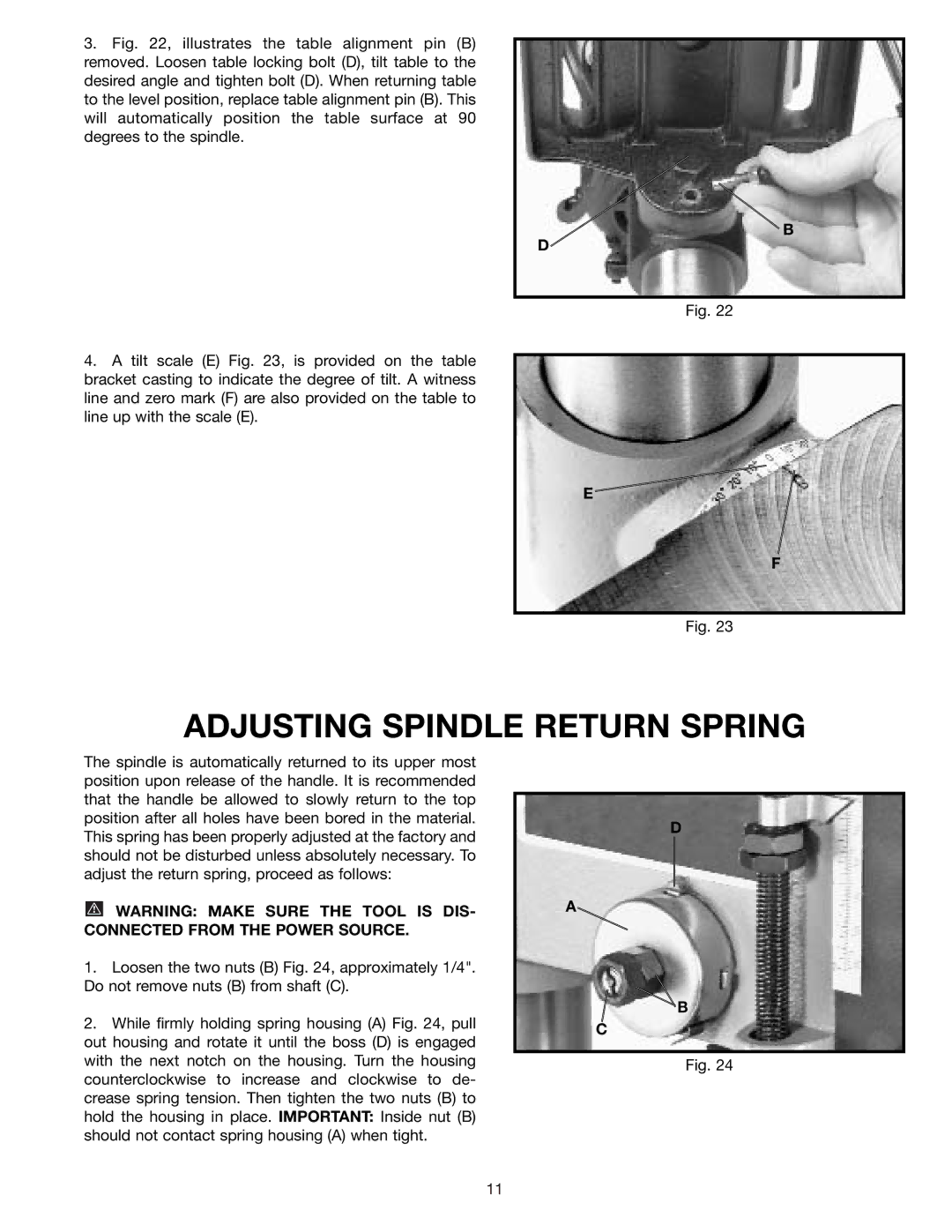
3.Fig. 22, illustrates the table alignment pin (B) removed. Loosen table locking bolt (D), tilt table to the desired angle and tighten bolt (D). When returning table to the level position, replace table alignment pin (B). This will automatically position the table surface at 90 degrees to the spindle.
4.A tilt scale (E) Fig. 23, is provided on the table bracket casting to indicate the degree of tilt. A witness line and zero mark (F) are also provided on the table to line up with the scale (E).
B
D
Fig. 22
E
F
Fig. 23
ADJUSTING SPINDLE RETURN SPRING
The spindle is automatically returned to its upper most position upon release of the handle. It is recommended that the handle be allowed to slowly return to the top position after all holes have been bored in the material. This spring has been properly adjusted at the factory and should not be disturbed unless absolutely necessary. To adjust the return spring, proceed as follows:
![]() WARNING: MAKE SURE THE TOOL IS DIS- CONNECTED FROM THE POWER SOURCE.
WARNING: MAKE SURE THE TOOL IS DIS- CONNECTED FROM THE POWER SOURCE.
1.Loosen the two nuts (B) Fig. 24, approximately 1/4". Do not remove nuts (B) from shaft (C).
2.While firmly holding spring housing (A) Fig. 24, pull out housing and rotate it until the boss (D) is engaged with the next notch on the housing. Turn the housing counterclockwise to increase and clockwise to de- crease spring tension. Then tighten the two nuts (B) to hold the housing in place. IMPORTANT: Inside nut (B) should not contact spring housing (A) when tight.
D
A
![]() B
B
C
Fig. 24
11