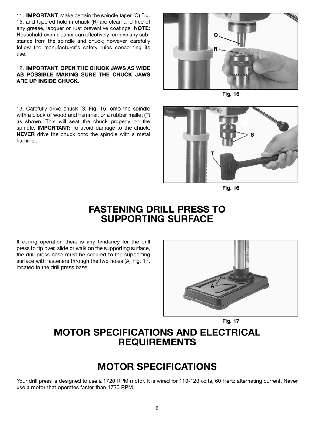
11.IMPORTANT: Make certain the spindle taper (Q) Fig. 15, and tapered hole in chuck (R) are clean and free of any grease, lacquer or rust preventive coatings. NOTE: Household oven cleaner can effectively remove any sub- stance from the spindle and chuck; however, carefully follow the manufacturer's safety rules concerning its use.
12.IMPORTANT: OPEN THE CHUCK JAWS AS WIDE AS POSSIBLE MAKING SURE THE CHUCK JAWS ARE UP INSIDE CHUCK.
13.Carefully drive chuck (S) Fig. 16, onto the spindle with a block of wood and hammer, or a rubber mallet (T) as shown. This will seat the chuck properly on the spindle. IMPORTANT: To avoid damage to the chuck, NEVER drive the chuck onto the spindle with a metal hammer.
Q
R
Fig. 15
![]() S
S
T
Fig. 16
FASTENING DRILL PRESS TO
SUPPORTING SURFACE
If during operation there is any tendency for the drill press to tip over, slide or walk on the supporting surface, the drill press base must be secured to the supporting surface with fasteners through the two holes (A) Fig. 17, located in the drill press base.
A ![]()
Fig. 17
MOTOR SPECIFICATIONS AND ELECTRICAL
REQUIREMENTS
MOTOR SPECIFICATIONS
Your drill press is designed to use a 1720 RPM motor. It is wired for
8