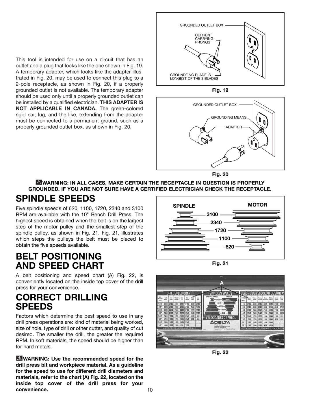
This tool is intended for use on a circuit that has an outlet and a plug that looks like the one shown in Fig. 19. A temporary adapter, which looks like the adapter illus- trated in Fig. 20, may be used to connect this plug to a
GROUNDED OUTLET BOX
CURRENT
CARRYING
PRONGS
GROUNDEING BLADE IS
LONGEST OF THE 3 BLADES
Fig. 19
GROUNDED OUTLET BOX
GROUNDING MEANS
ADAPTER
Fig. 20
![]() WARNING: IN ALL CASES, MAKE CERTAIN THE RECEPTACLE IN QUESTION IS PROPERLY GROUNDED. IF YOU ARE NOT SURE HAVE A CERTIFIED ELECTRICIAN CHECK THE RECEPTACLE.
WARNING: IN ALL CASES, MAKE CERTAIN THE RECEPTACLE IN QUESTION IS PROPERLY GROUNDED. IF YOU ARE NOT SURE HAVE A CERTIFIED ELECTRICIAN CHECK THE RECEPTACLE.
SPINDLE SPEEDS
Five spindle speeds of 620, 1100, 1720, 2340 and 3100 RPM are available with the 10" Bench Drill Press. The highest speed is obtained when the belt is on the largest step of the motor pulley and the smallest step of the spindle pulley, as shown in Fig. 21. Fig. 21, illustrates which steps the pulleys the belt must be placed to obtain the five speeds available.
BELT POSITIONING
AND SPEED CHART
A belt positioning and speed chart (A) Fig. 22, is conveniently located on the inside top cover of the drill press for your convenience.
CORRECT DRILLING
SPEEDS
Factors which determine the best speed to use in any drill press operations are: kind of material being worked, size of hole, type of drill or other cutter, and quality of cut desired. The smaller the drill, the greater the required RPM. In soft materials, the speed should be higher than for hard metals.
![]() WARNING: Use the recommended speed for the drill press bit and workpiece material. As a guideline for the speed to use for different drill diameters and materials, refer to the chart (A) Fig. 22, located on the inside top cover of the drill press for your
WARNING: Use the recommended speed for the drill press bit and workpiece material. As a guideline for the speed to use for different drill diameters and materials, refer to the chart (A) Fig. 22, located on the inside top cover of the drill press for your
convenience.10
SPINDLEMOTOR
3100
2340
1720
1100
620
Fig. 21
A
Fig. 22
