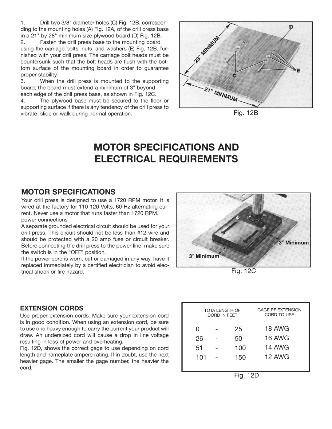
1.Drill two 3/8" diameter holes (C) Fig. 12B, correspon- ding to the mounting holes (A) Fig. 12A, of the drill press base in a 21" by 28" minimum size plywood board (D) Fig. 12B.
2.Fasten the drill press base to the mounting board using the carriage bolts, nuts, and washers (E) Fig. 12B, fur- nished with your drill press. The carriage bolt heads must be countersunk such that the bolt heads are flush with the bot- tom surface of the mounting board in order to guarantee proper stability.
3.When the drill press is mounted to the supporting board, the board must extend a minimum of 3" beyond each edge of the drill press base, as shown in Fig. 12C.
4.The plywood base must be secured to the floor or supporting surface if there is any tendency of the drill press to
vibrate, slide or walk during normal operation. | Fig. 12B |
MOTOR SPECIFICATIONS AND
ELECTRICAL REQUIREMENTS
MOTOR SPECIFICATIONS
Your drill press is designed to use a 1720 RPM motor. It is wired at the factory for
A separate grounded electrical circuit should be used for your drill press. This circuit should not be less than #12 wire and should be protected with a 20 amp fuse or circuit breaker. Before connecting the drill press to the power line, make sure the switch is in the “OFF” position.
If the power cord is worn, cut or damaged in any way, have it replaced immediately by a certified electrician to avoid elec- trical shock or fire hazard.
EXTENSION CORDS
Use proper extension cords. Make sure your extension cord is in good condition. When using an extension cord, be sure to use one heavy enough to carry the current your product will draw. An undersized cord will cause a drop in line voltage resulting in loss of power and overheating.
Fig. 12D, shows the correct gage to use depending on cord length and nameplate ampere rating. If in doubt, use the next heavier gage. The smaller the gage number, the heavier the cord.
Fig. 12C
| TOTA LENGTH OF |
|
| GAGE PF EXTENSION | ||||
|
| CORD IN FEET |
|
|
| CORD TO USE | ||
|
|
|
|
|
|
|
|
|
|
|
|
|
|
|
|
|
|
|
|
|
|
|
|
| 18 AWG | |
0 |
| - | 25 |
| ||||
26 | - | 50 |
|
|
| 16 AWG |
| |
51 | - | 100 |
|
| 14 AWG |
| ||
101 | - | 150 |
|
| 12 AWG |
| ||
|
|
|
|
|
|
|
|
|
Fig. 12D