UNPACKING
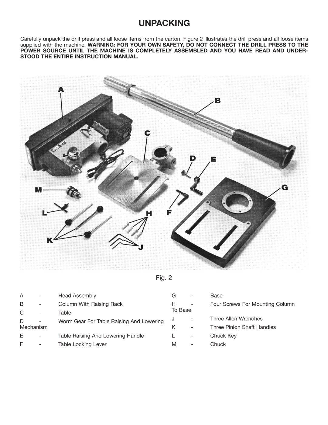
Carefully unpack the drill press and all loose items from the carton. Figure 2 illustrates the drill press and all loose items supplied with the machine. WARNING: FOR YOUR OWN SAFETY, DO NOT CONNECT THE DRILL PRESS TO THE
POWER SOURCE UNTIL THE MACHINE IS COMPLETELY ASSEMBLED AND YOU HAVE READ AND UNDER- STOOD THE ENTIRE INSTRUCTION MANUAL.
Fig. 2
A | - | Head Assembly | G | - | Base | |
B | - | Column With Raising Rack | H | - | Four Screws For Mounting Column | |
C | - | Table | To Base |
|
| |
J | - | Three Allen Wrenches | ||||
D | - | Worm Gear For Table Raising And Lowering | ||||
K | - | Three Pinion Shaft Handles | ||||
Mechanism |
| |||||
E | - | Table Raising And Lowering Handle | L | - | Chuck Key | |
F | - | Table Locking Lever | M | - | Chuck | |
