ADJUSTING SPRING TENSION ON FEED ROLLERS
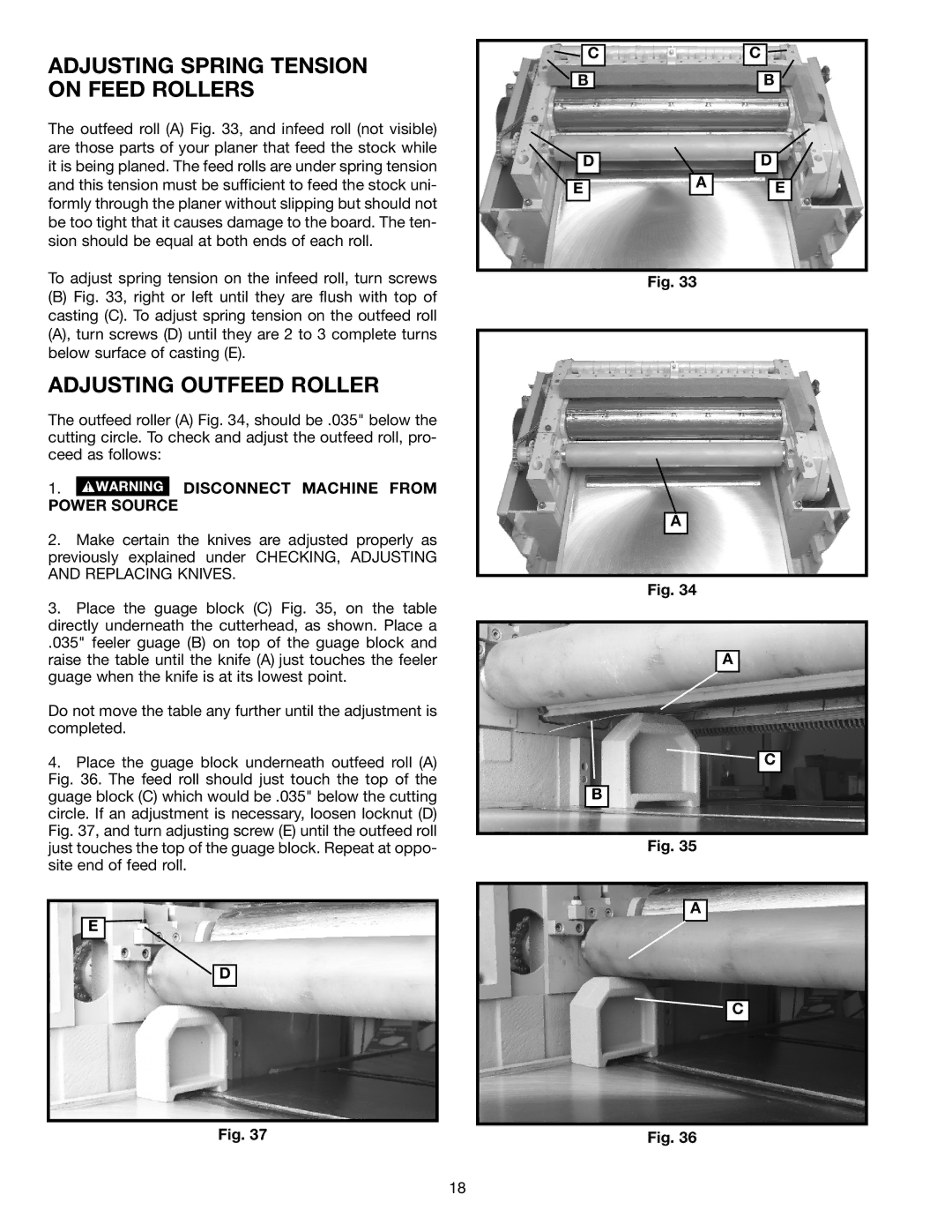
The outfeed roll (A) Fig. 33, and infeed roll (not visible) are those parts of your planer that feed the stock while it is being planed. The feed rolls are under spring tension and this tension must be sufficient to feed the stock uni- formly through the planer without slipping but should not be too tight that it causes damage to the board. The ten- sion should be equal at both ends of each roll.
To adjust spring tension on the infeed roll, turn screws
(B)Fig. 33, right or left until they are flush with top of casting (C). To adjust spring tension on the outfeed roll (A), turn screws (D) until they are 2 to 3 complete turns below surface of casting (E).
ADJUSTING OUTFEED ROLLER
The outfeed roller (A) Fig. 34, should be .035" below the cutting circle. To check and adjust the outfeed roll, pro- ceed as follows:
1. DISCONNECT MACHINE FROM POWER SOURCE
2.Make certain the knives are adjusted properly as previously explained under CHECKING, ADJUSTING AND REPLACING KNIVES.
3.Place the guage block (C) Fig. 35, on the table directly underneath the cutterhead, as shown. Place a
.035" feeler guage (B) on top of the guage block and raise the table until the knife (A) just touches the feeler guage when the knife is at its lowest point.
Do not move the table any further until the adjustment is completed.
4.Place the guage block underneath outfeed roll (A) Fig. 36. The feed roll should just touch the top of the guage block (C) which would be .035" below the cutting circle. If an adjustment is necessary, loosen locknut (D) Fig. 37, and turn adjusting screw (E) until the outfeed roll just touches the top of the guage block. Repeat at oppo- site end of feed roll.
E ![]()
D
Fig. 37
|
|
| C |
|
|
| C |
|
| |||||||
|
|
|
|
|
|
|
|
|
| |||||||
| B |
|
|
|
|
|
| B | ||||||||
|
|
|
|
|
|
|
|
|
|
|
|
|
|
|
|
|
|
|
|
|
|
|
|
|
|
|
|
|
|
|
|
|
|
|
| D |
|
|
|
|
|
| D | |||||||
|
|
|
|
|
|
|
|
|
|
|
|
|
|
|
|
|
|
|
|
|
|
|
|
| A |
|
|
|
|
|
|
| |
| E |
|
|
|
|
|
|
| E | |||||||
|
|
|
|
|
|
|
|
|
|
|
|
|
|
|
|
|
Fig. 33
A
Fig. 34
A
![]()
![]() C
C
B
Fig. 35
A
![]()
![]() C
C
Fig. 36
18