ASSEMBLY
STAND
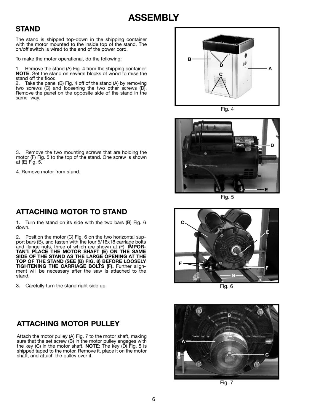
The stand is shipped
To make the motor operational, do the following:
1.Remove the stand (A) Fig. 4 from the shipping container. NOTE: Set the stand on several blocks of wood to raise the stand off the floor.
2.Take the panel (B) Fig. 4 off of the stand (A) by removing two screws (C) and loosening the two other screws (D). Remove the panel on the opposite side of the stand in the same way.
B
D
C
A
3.Remove the two mounting screws that are holding the motor (F) Fig. 5 to the top of the stand. One screw is shown at (E) Fig. 5.
4.Remove motor from stand.
Fig. 4
![]() D
D
F
E
Fig. 5
ATTACHING MOTOR TO STAND
1.Turn the stand on its side with the two bars (B) Fig. 6 down.
2.Position the motor (C) Fig. 6 on the two horizontal sup- port bars (B), and fasten with the four 5/16x18 carriage bolts and flange nuts, three of which are shown at (F). IMPOR-
TANT: PLACE THE MOTOR SHAFT (E) ON THE SAME SIDE OF THE STAND AS THE LARGE OPENING AT THE TOP OF THE STAND (SEE (B) FIG. 8) BEFORE LOOSELY TIGHTENING THE CARRIAGE BOLTS (F). Further align- ment will be necessary after the saw is attached to the stand.
3.Carefully turn the stand right side up.
ATTACHING MOTOR PULLEY
Attach the motor pulley (A) Fig. 7 to the motor shaft, making sure that the set screw (B) in the motor pulley engages with the key (C) in the motor shaft. NOTE: The key (D) Fig. 5 is shipped taped to the motor. Remove it, place it on the motor shaft, and attach the pulley over it.
C
E
F
F
B
Fig. 6
B
A
C
Fig. 7
6