HOW TO REMOVE AND REPLACE THE FEED BELT
![]() To reduce the risk of injury, turn unit off and disconnect it from power source before installing and removing accessories, before adjusting or when making repairs. An accidental
To reduce the risk of injury, turn unit off and disconnect it from power source before installing and removing accessories, before adjusting or when making repairs. An accidental
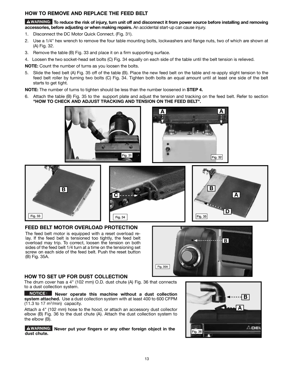
1.Disconnect the DC Motor Quick Connect. (Fig. 31).
2.Use a 1/4" hex wrench to remove the four table mounting bolts, lockwashers and flange nuts, two of which are shown at
(A)Fig. 32.
3.Remove the table (B) Fig. 33 and place it on a firm supporting surface.
4.Loosen the two
NOTE: Count the number of turns as you loosen the bolts.
5.Slide the feed belt (A) Fig. 35 off of the table (B). Place the new feed belt on the table and
NOTE: The number of turns to tighten should be less than the number loosened in STEP 4.
6.Attach the table (B) Fig. 35 to the support plate and adjust the tension and tracking on the feed belt. Refer to section
"HOW TO CHECK AND ADJUST TRACKING AND TENSION ON THE FEED BELT".
A
A
Fig. 31
Fig. 32
|
|
|
|
|
|
|
|
|
|
|
|
|
|
|
|
|
|
|
|
|
|
|
|
|
|
|
|
|
|
|
|
|
|
|
|
|
|
|
|
|
|
|
|
|
|
|
|
|
|
|
|
|
|
|
|
|
|
| B |
|
|
|
|
|
|
|
|
| B |
|
|
|
|
|
|
|
|
|
| ||||||||
|
|
|
|
|
|
|
|
|
|
|
|
|
|
| |||||||
|
|
|
|
|
|
|
|
|
|
|
|
|
|
|
|
|
| A |
|
| |
|
|
|
|
|
|
|
| C |
|
|
| ||||||||||
|
|
|
|
|
|
|
|
|
|
|
|
|
|
|
|
| D | ||||
|
|
|
|
|
|
|
|
|
|
|
|
|
|
|
|
| |||||
| Fig. 33 |
|
|
|
|
|
| Fig. 34 |
|
|
|
| Fig. 35 |
|
|
|
|
|
|
| |
|
|
|
|
|
|
|
|
|
|
|
|
|
|
|
|
|
|
|
|
|
|
FEED BELT MOTOR OVERLOAD PROTECTION |
|
|
|
|
|
|
|
|
|
| |||||||||||
|
|
|
|
|
|
|
|
|
| ||||||||||||
The feed belt motor is equipped with a reset overload re- |
|
|
|
|
|
|
|
|
| ||||||||||||
lay. If the feed belt is tensioned too tightly, the feed belt |
|
|
|
|
|
|
|
|
| ||||||||||||
|
|
|
| B |
|
|
|
| |||||||||||||
overload may trip. To correct, loosen the tension on both |
|
|
|
|
| ||||||||||||||||
|
|
|
|
|
|
|
|
| |||||||||||||
sides of the feed belt 1/4 turn at a time on the tensioning set |
|
|
|
|
|
|
|
|
| ||||||||||||
screw on each side of the feed belt. Push the reset button |
|
|
|
|
|
|
|
|
| ||||||||||||
(B) Fig. 35A. |
|
|
|
|
|
|
|
|
|
|
|
|
|
|
|
|
|
|
| ||
Fig. 35A
HOW TO SET UP FOR DUST COLLECTION
The drum cover has a 4" (102 mm) O.D. dust chute (A) Fig. 36 that connects to a dust collection system.
NOTICE ![]() Never operate this machine without a dust collection
Never operate this machine without a dust collection
system attached. Use a dust collection system with at least 400 to 600 CFPM (11.3 to 17 m3/min) capacity.
Attach a 4" (102 mm) hose to the hood, or attach an accessory dust collector elbow (B) Fig. 36 to the dust chute (A). Attach the dust collection system to the elbow (B).
![]() Never put your fingers or any other foreign object in the dust chute.
Never put your fingers or any other foreign object in the dust chute.
Fig. 36
![]()
![]() B
B
![]()
![]() A
A
13
