POWER TAKE-OFF SHAFT
1.DISCONNECT TOOL FROM POWER SOURCE.
2.A power
3.For access to the power
4.WARNING: Unguarded rotating shafts (C) Fig 41 can create an entanglement hazard. ALWAYS COVER THE POWER
C
B
A
Fig. 41
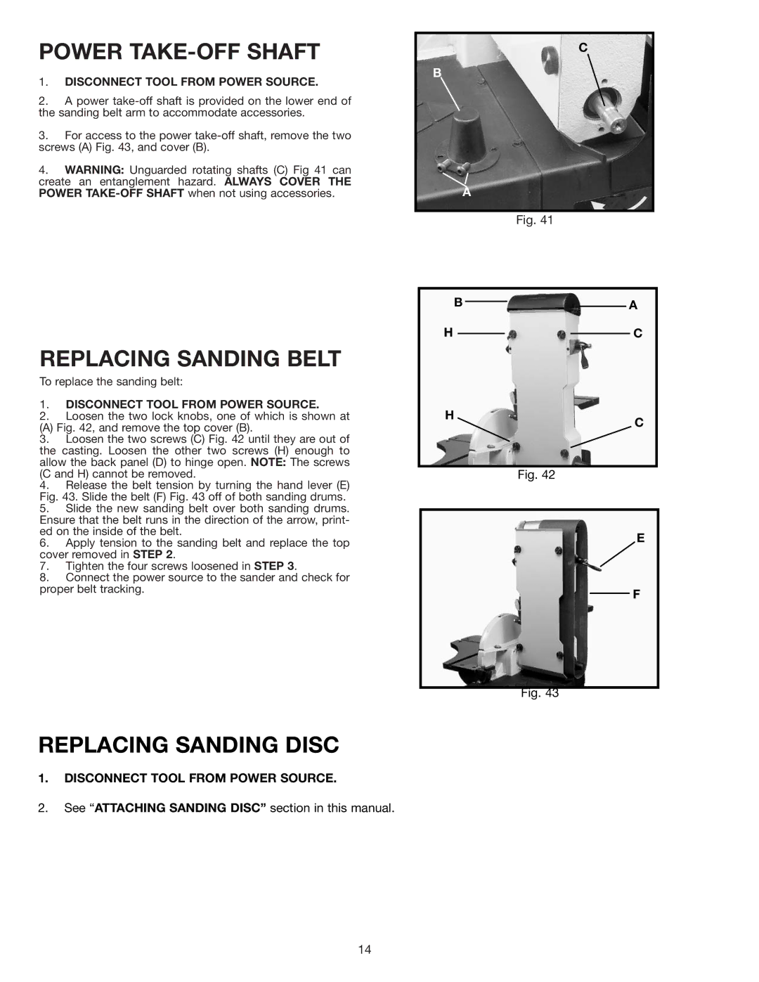
REPLACING SANDING BELT
To replace the sanding belt:
1.DISCONNECT TOOL FROM POWER SOURCE.
2.Loosen the two lock knobs, one of which is shown at
(A) Fig. 42, and remove the top cover (B).
3.Loosen the two screws (C) Fig. 42 until they are out of the casting. Loosen the other two screws (H) enough to allow the back panel (D) to hinge open. NOTE: The screws (C and H) cannot be removed.
4.Release the belt tension by turning the hand lever (E) Fig. 43. Slide the belt (F) Fig. 43 off of both sanding drums.
5.Slide the new sanding belt over both sanding drums. Ensure that the belt runs in the direction of the arrow, print- ed on the inside of the belt.
6.Apply tension to the sanding belt and replace the top cover removed in STEP 2.
7.Tighten the four screws loosened in STEP 3.
8.Connect the power source to the sander and check for proper belt tracking.
REPLACING SANDING DISC
1.DISCONNECT TOOL FROM POWER SOURCE.
2.See “ATTACHING SANDING DISC” section in this manual.
B ![]()
![]() A
A
HC
H
C
Fig. 42
E
F
Fig. 43
14