E.

1


2


2


3

4

5 6

7

8

9

F.

1/2” (12.7mm) IPS

2

3

3

1

3


1 2


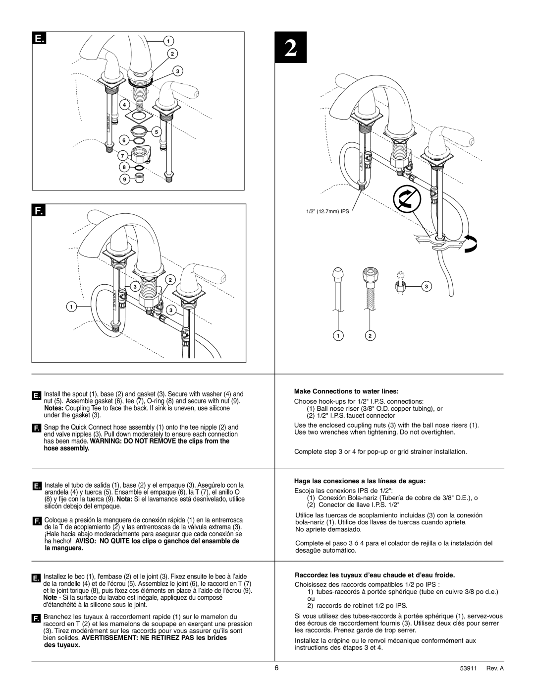
Install the spout (1), base (2) and gasket (3). Secure with washer (4) and

Make Connections to water lines:


E.


nut (5). Assemble gasket (6), tee (7), O-ring (8) and secure with nut (9).

Choose hook-ups for 1/2" I.P.S. connections:


Notes: Coupling Tee to face the back. If sink is uneven, use silicone

(1) Ball nose riser (3/8" O.D. copper tubing), or


under the gasket (3).

(2) 1/2" I.P.S. faucet connector


Snap the Quick Connect hose assembly (1) onto the tee nipple (2) and

Use the enclosed coupling nuts (3) with the ball nose risers (1).


F.


end valve nipples (3). Pull down moderately to ensure each connection

Use two wrenches when tightening. Do not overtighten.


has been made. WARNING: DO NOT REMOVE the clips from the


hose assembly.

Complete step 3 or 4 for pop-up or grid strainer installation.


Instale el tubo de salida (1), base (2) y el empaque (3). Asegúrelo con la

Haga las conexiones a las líneas de agua:


E.


Escoja las conexions IPS de 1/2":


arandela (4) y tuerca (5). Ensamble el empaque (6), la T (7), el anillo O


(8) y fije con la tuerca (9). Nota: Si el lavamanos está desnivelado, utilice

(1)  Conexión Bola-nariz (Tubería de cobre de 3/8" D.E.), o


silicón debajo del empaque.

(2)  Conector de llave I.P.S. 1/2"


Coloque a presión la manguera de conexión rápida (1) en la entrerrosca

Utilice las tuercas de acoplamiento incluidas (3) con la conexión


F.


bola-nariz (1). Utilice dos llaves de tuercas cuando apriete.


de la T de acoplamiento (2) y las entrerroscas de la válvula extrema (3).

No apriete demasiado.


¡Hale hacia abajo moderadamente para asegurar que cada conexión se


ha hecho! AVISO: NO QUITE los clips o ganchos del ensamble de

Complete el paso 3 ó 4 para el colador de rejilla o la instalación del


la manguera.


desagüe automático.


Installez le bec (1), l'embase (2) et le joint (3). Fixez ensuite le bec à l’aide

Raccordez les tuyaux d’eau chaude et d’eau froide.


E.


de la rondelle (4) et de l’écrou (5). Assemblez le joint (6), le raccord en T (7)

Choisissez des raccords compatibles 1/2 po IPS :


et le joint torique (8), puis fixez ces éléments en place à l’aide de l’écrou (9).

1)  tubes-raccords à portée sphérique (tube en cuivre 3/8 po d.e.)


Note - Si la surface du lavabo est inégale, appliquez du composé

ou


d’étanchéité à la silicone sous le joint.

2)  raccords de robinet 1/2 po IPS.


Branchez les tuyaux à raccordement rapide (1) sur le mamelon du

Si vous utilisez des tubes-raccords à portée sphérique (1), servez-vous


F.


raccord en T (2) et les mamelons de soupape en exerçant une pression

des écrous de raccordement fournis (3). Utilisez deux clés pour serrer


(3). Tirez modérément sur les raccords pour vous assurer qu’ils sont

les raccords. Prenez garde de trop serrer.


bien solides. AVERTISSEMENT: NE RETIREZ PAS les brides

Installez la crépine ou le renvoi mécanique conformément aux


des tuyaux.


instructions des étapes 3 et 4.


6

53911      Rev. A

Page 6
Image 6
Delta 3584 Series manual Ha hecho! Aviso no Quite los clips o ganchos del ensamble de

3584 Series specifications

The Delta 3584 Series is a cutting-edge range of industrial electronics that has been making waves in various sectors, including manufacturing, automation, and telecommunications. This series is designed to meet the demands of modern industry while providing robust performance, efficiency, and versatility.

One of the defining features of the Delta 3584 Series is its advanced processing capability. Equipped with a high-performance microcontroller, the devices can handle complex tasks with ease, allowing for real-time data processing and analysis. This makes it ideal for applications where speed and accuracy are critical, such as in robotics and automated production lines.

In addition to processing power, the Delta 3584 Series utilizes a modular design, allowing users to customize their setups by integrating various functional modules as needed. This flexibility means that businesses can adapt the system to their specific requirements without the need for extensive overhauls or complete replacements. The series also incorporates an extensive range of connectivity options, including Ethernet, USB, and serial communication interfaces, enhancing its interoperability with existing systems and equipment.

Another key characteristic of the Delta 3584 Series is its commitment to energy efficiency. The devices are engineered to minimize power consumption while maintaining optimal performance levels. This not only helps reduce operational costs but also aligns with global sustainability goals by lessening the environmental impact of industrial processes.

The series boasts robust security features, which are essential in today’s landscape where cyber threats are a growing concern. With built-in encryption and secure communication protocols, the Delta 3584 Series ensures that sensitive data remains protected, contributing to the integrity of business operations.

User-friendly interfaces are another highlight of the Delta 3584 Series. Touchscreen capabilities, intuitive navigation, and customizable dashboards make it easy for operators to monitor and control processes efficiently, thus minimizing training time and maximizing productivity.

Overall, the Delta 3584 Series stands out as a versatile, reliable, and forward-thinking technology solution for industries looking to innovate and improve their operational efficiencies. With its combination of advanced features, modular design, energy efficiency, security, and user-friendly interfaces, this series is well-suited to support the industrial landscape of tomorrow.