FASTENING JOINTER TO SUPPORTING SURFACE
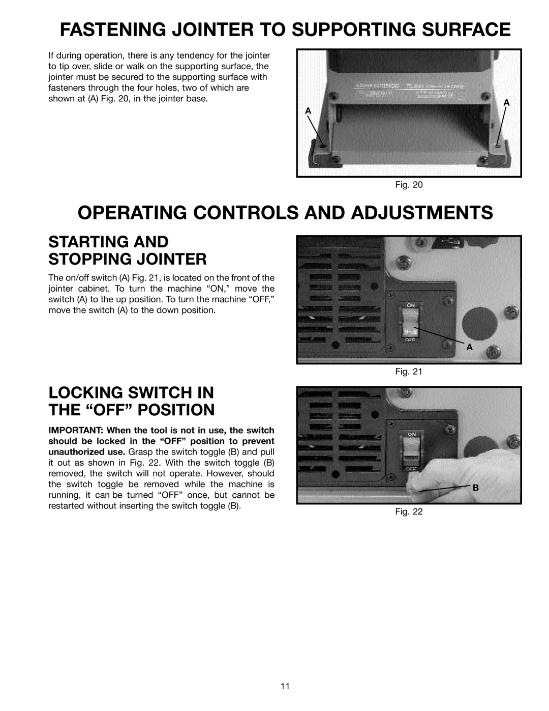
If during operation, there is any tendency for the jointer |
|
to tip over, slide or walk on the supporting surface, the |
|
jointer must be secured to the supporting surface with |
|
fasteners through the four holes, two of which are |
|
shown at (A) Fig. 20, in the jointer base. | A |
| |
| A |
Fig. 20
OPERATING CONTROLS AND ADJUSTMENTS
STARTING AND
STOPPING JOINTER
The on/off switch (A) Fig. 21, is located on the front of the jointer cabinet. To turn the machine “ON,” move the switch (A) to the up position. To turn the machine “OFF,” move the switch (A) to the down position.
A
Fig. 21
LOCKING SWITCH IN
THE “OFF” POSITION
IMPORTANT: When the tool is not in use, the switch should be locked in the “OFF” position to prevent unauthorized use. Grasp the switch toggle (B) and pull it out as shown in Fig. 22. With the switch toggle (B) removed, the switch will not operate. However, should the switch toggle be removed while the machine is running, it can be turned “OFF” once, but cannot be restarted without inserting the switch toggle (B).
B
Fig. 22
11