EXTENSION CORDS
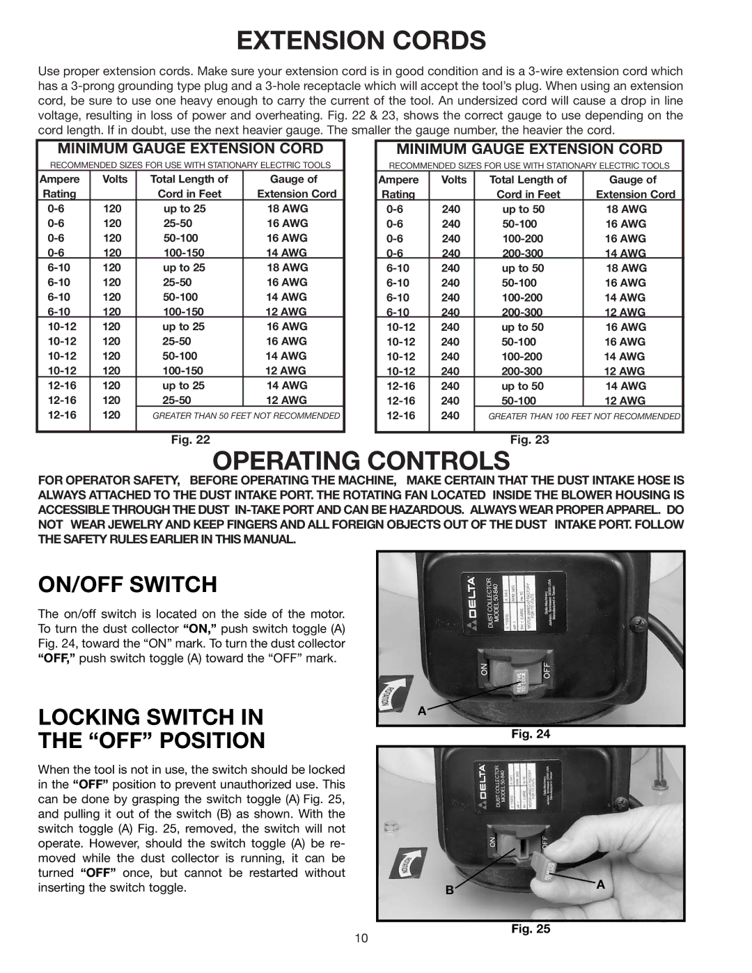
Use proper extension cords. Make sure your extension cord is in good condition and is a
MINIMUM GAUGE EXTENSION CORD
RECOMMENDED SIZES FOR USE WITH STATIONARY ELECTRIC TOOLS
Ampere | Volts | Total Length of | Gauge of |
Rating |
| Cord in Feet | Extension Cord |
120 | up to 25 | 18 AWG | |
120 | 16 AWG | ||
120 | 16 AWG | ||
120 | 14 AWG | ||
120 | up to 25 | 18 AWG | |
120 | 16 AWG | ||
120 | 14 AWG | ||
120 | 12 AWG | ||
120 | up to 25 | 16 AWG | |
120 | 16 AWG | ||
120 | 14 AWG | ||
120 | 12 AWG | ||
120 | up to 25 | 14 AWG | |
120 | 12 AWG | ||
120 | GREATER THAN 50 FEET NOT RECOMMENDED | ||
|
|
|
|
MINIMUM GAUGE EXTENSION CORD
RECOMMENDED SIZES FOR USE WITH STATIONARY ELECTRIC TOOLS
Ampere | Volts | Total Length of | Gauge of |
Rating |
| Cord in Feet | Extension Cord |
240 | up to 50 | 18 AWG | |
240 | 16 AWG | ||
240 | 16 AWG | ||
240 | 14 AWG | ||
240 | up to 50 | 18 AWG | |
240 | 16 AWG | ||
240 | 14 AWG | ||
240 | 12 AWG | ||
240 | up to 50 | 16 AWG | |
240 | 16 AWG | ||
240 | 14 AWG | ||
240 | 12 AWG | ||
240 | up to 50 | 14 AWG | |
240 | 12 AWG | ||
240 | GREATER THAN 100 FEET NOT RECOMMENDED | ||
|
|
|
|
Fig. 22Fig. 23
OPERATING CONTROLS
FOR OPERATOR SAFETY, BEFORE OPERATING THE MACHINE, MAKE CERTAIN THAT THE DUST INTAKE HOSE IS ALWAYS ATTACHED TO THE DUST INTAKE PORT. THE ROTATING FAN LOCATED INSIDE THE BLOWER HOUSING IS ACCESSIBLE THROUGH THE DUST
ON/OFF SWITCH
The on/off switch is located on the side of the motor. To turn the dust collector “ON,” push switch toggle (A) Fig. 24, toward the “ON” mark. To turn the dust collector “OFF,” push switch toggle (A) toward the “OFF” mark.
LOCKING SWITCH IN
THE “OFF” POSITION
When the tool is not in use, the switch should be locked in the “OFF” position to prevent unauthorized use. This can be done by grasping the switch toggle (A) Fig. 25, and pulling it out of the switch (B) as shown. With the switch toggle (A) Fig. 25, removed, the switch will not operate. However, should the switch toggle (A) be re- moved while the dust collector is running, it can be turned “OFF” once, but cannot be restarted without inserting the switch toggle.
A
Fig. 24
BA
Fig. 25
10
