ASSEMBLING SUPPORT TUBE A N D M O TO R A N D B L O W E R ASSEMBLY TO BASE
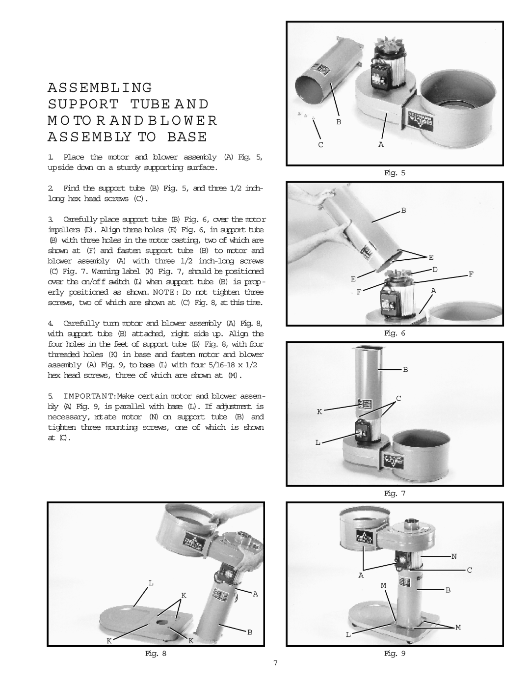
1. | Place the motor and blower assembly (A) Fig. 5, |
upside down on a sturdy supporting surface. | |
2. | Find the support tube (B) Fig. 5, and three 1/2 inch- |
long hex head screws (C). | |
3. | Carefully place support tube (B) Fig. 6, over the motor |
impellers (D). Align three holes (E) Fig. 6, in support tube | |
(B) with three holes in the motor casting, two of which are | |
shown at (F) and fasten support tube (B) to motor and | |
blower assembly (A) with three 1/2 | |
(C) Fig. 7. Warning label (K) Fig. 7, should be positioned | |
B
CA
Fig. 5
B
![]() E
E
D
over the on/off switch (L) when support tube (B) is prop- |
E
F
erly positioned as shown. NOTE: Do not tighten three |
screws, two of which are shown at (C) Fig. 8, at this time. |
4. Carefully turn motor and blower assembly (A) Fig. 8, |
with support tube (B) attached, right side up. Align the |
four holes in the feet of support tube (B) Fig. 8, with four |
threaded holes (K) in base and fasten motor and blower |
assembly (A) Fig. 9, to base (L) with four |
hex head screws, three of which are shown at (M). |
5. IMPORTANT:Make certain motor and blower assem- |
bly (A) Fig. 9, is parallel with base (L). If adjustment is |
necessary, rotate motor (N) on support tube (B) and |
tighten three mounting screws, one of which is shown |
at (C). |
F ![]() A
A
Fig. 6
B
C
K ![]()
L ![]()
Fig. 7
N
A
C
L
K ![]() A
A
![]() B
B
KK
Fig. 8
M
B
![]() M
M
L
Fig. 9
7