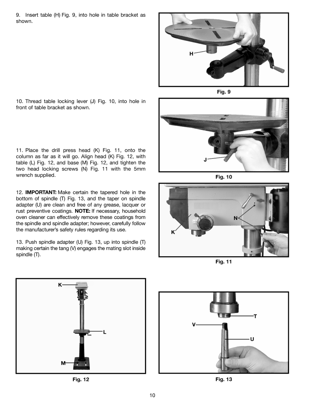
9.Insert table (H) Fig. 9, into hole in table bracket as shown.
10.Thread table locking lever (J) Fig. 10, into hole in front of table bracket as shown.
11.Place the drill press head (K) Fig. 11, onto the column as far as it will go. Align head (K) Fig. 12, with table (L) Fig. 12, and base (M) Fig. 12, and tighten the two head locking screws (N) Fig. 11 with the 5mm wrench supplied.
12.IMPORTANT: Make certain the tapered hole in the bottom of spindle (T) Fig. 13, and the taper on spindle adapter (U) are clean and free of any grease, lacquer or rust preventive coatings. NOTE: If necessary, household oven cleaner can effectively remove these coatings from the spindle and spindle adapter; however, carefully follow the manufacturer’s safety rules regarding its use.
13.Push spindle adapter (U) Fig. 13, up into spindle (T) making certain the tang (V) engages the mating slot inside spindle (T).
K
L
M
Fig. 12
H
Fig. 9
J![]()
Fig. 10
N![]()
K
Fig. 11
T
V
U
Fig. 13
10