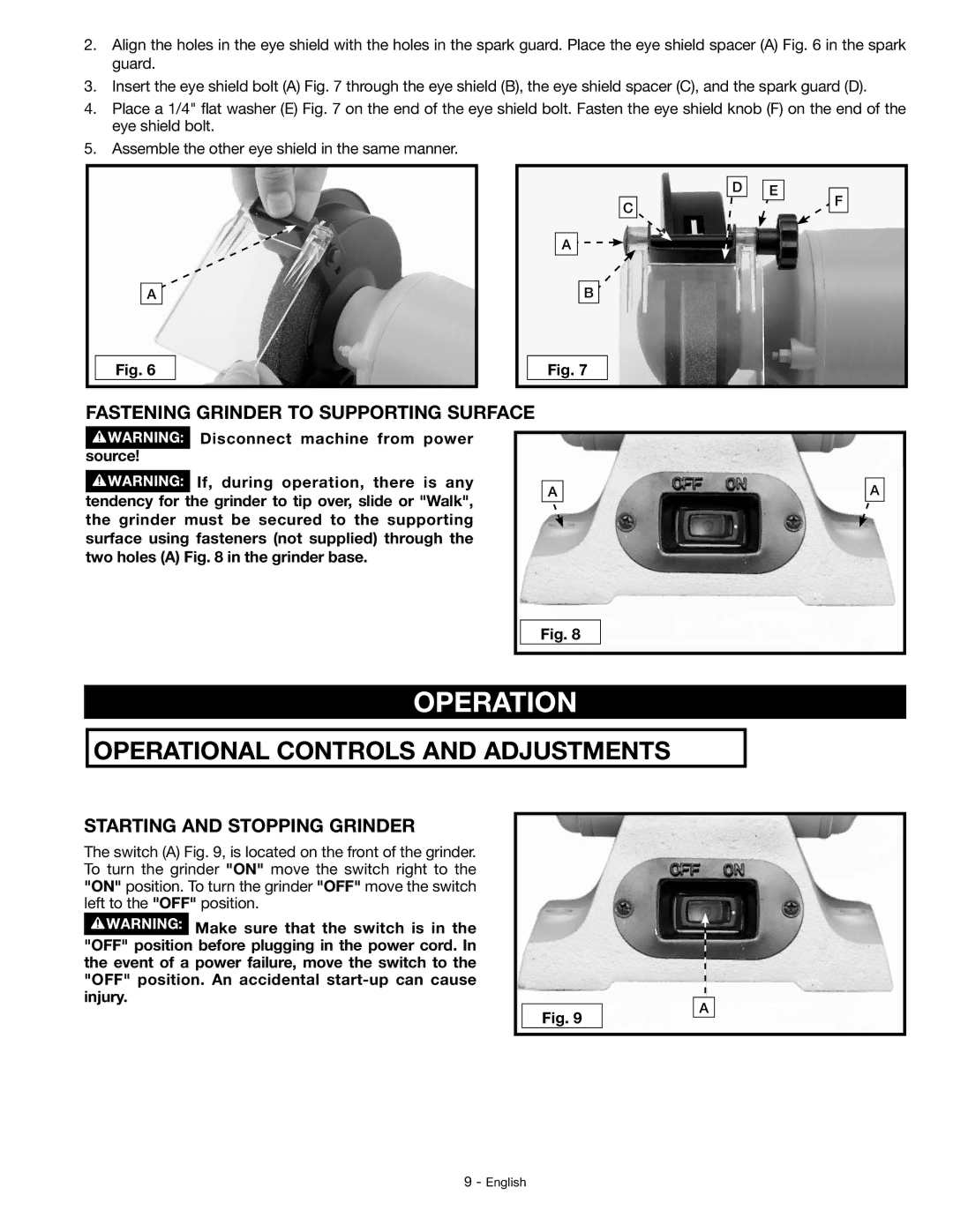
2.Align the holes in the eye shield with the holes in the spark guard. Place the eye shield spacer (A) Fig. 6 in the spark guard.
3.Insert the eye shield bolt (A) Fig. 7 through the eye shield (B), the eye shield spacer (C), and the spark guard (D).
4.Place a 1/4" flat washer (E) Fig. 7 on the end of the eye shield bolt. Fasten the eye shield knob (F) on the end of the eye shield bolt.
5.Assemble the other eye shield in the same manner.
D
E
C
A![]()
F
A
B
Fig. 6
Fig. 7
FASTENING GRINDER TO SUPPORTING SURFACE
![]() Disconnect machine from power source!
Disconnect machine from power source!
|
|
| If, during operation, there is any |
| |
|
|
| A | ||
|
|
| |||
tendency for the grinder to tip over, slide or "Walk", | |||||
| |||||
| |||||
the grinder must be secured to the supporting |
| ||||
surface using fasteners (not supplied) through the |
| ||||
two holes (A) Fig. 8 in the grinder base. |
| ||||
A
Fig. 8
OPERATION
OPERATIONAL CONTROLS AND ADJUSTMENTS
STARTING AND STOPPING GRINDER
The switch (A) Fig. 9, is located on the front of the grinder. To turn the grinder "ON" move the switch right to the "ON" position. To turn the grinder "OFF" move the switch left to the "OFF" position.
![]() Make sure that the switch is in the "OFF" position before plugging in the power cord. In the event of a power failure, move the switch to the "OFF" position. An accidental
Make sure that the switch is in the "OFF" position before plugging in the power cord. In the event of a power failure, move the switch to the "OFF" position. An accidental
Fig. 9
A
9 - English