ATTACHING BELT TABLE
B |
D |
A |
C |
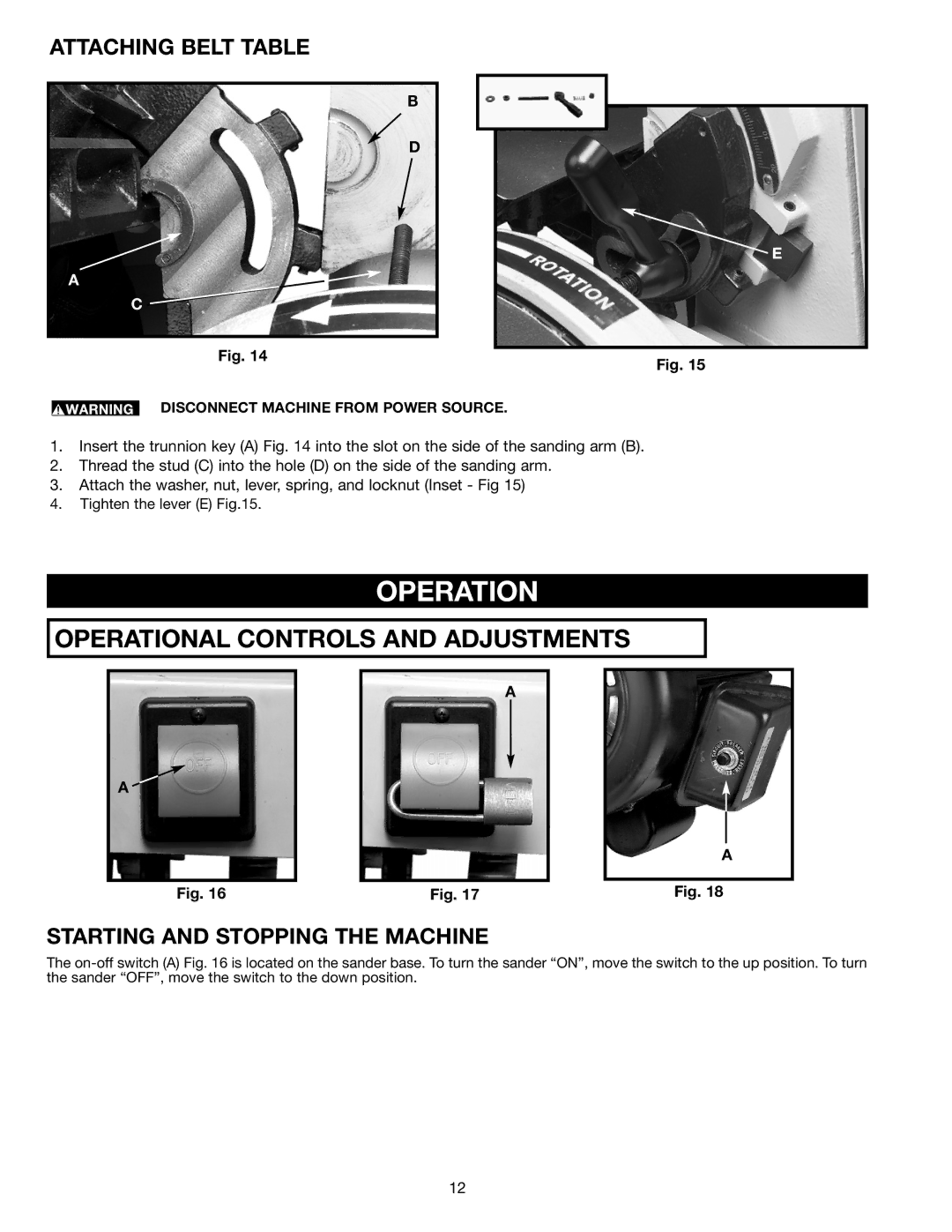
Fig. 14
E
Fig. 15
DISCONNECT MACHINE FROM POWER SOURCE.
1.Insert the trunnion key (A) Fig. 14 into the slot on the side of the sanding arm (B).
2.Thread the stud (C) into the hole (D) on the side of the sanding arm.
3.Attach the washer, nut, lever, spring, and locknut (Inset - Fig 15)
4.Tighten the lever (E) Fig.15.
OPERATION
OPERATIONAL CONTROLS AND ADJUSTMENTS
A ![]()
Fig. 16
A
Fig. 17
A
Fig. 18
STARTING AND STOPPING THE MACHINE
The
12