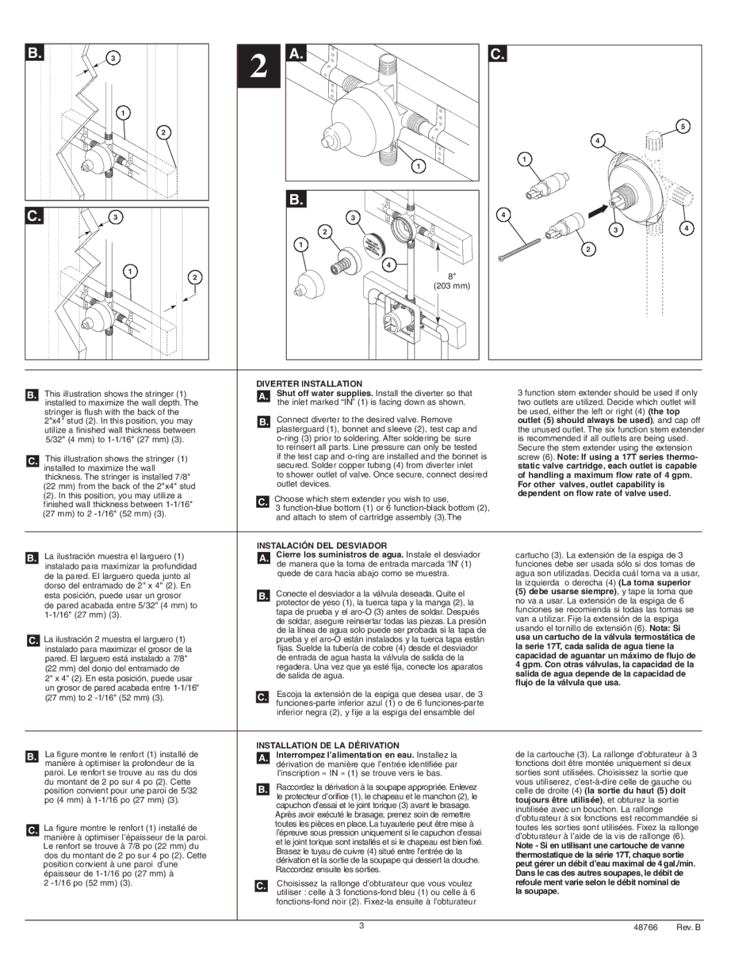
| | | | | | | DIVERTER INSTALLATION | 3 function stem extender should be used if only |
| B. | | | | This illustration shows the stringer (1) | | | | | Shut off water supplies. Install the diverter so that |
| A. |
| | | | | installed to maximize the wall depth. The | | | the inlet marked “IN” (1) is facing down as shown. | two outlets are utilized. Decide which outlet will |
| |
| | | | |
| | | | | stringer is flush with the back of the | | | | | Connect diverter to the desired valve. Remove | be used, either the left or right (4) (the top |
| | | | | 2"x4" stud (2). In this position, you may | | B. | | outlet (5) should always be used), and cap off |
| | | | | utilize a finished wall thickness between | | | | | plasterguard (1), bonnet and sleeve (2), test cap and | the unused outlet. The six function stem extender |
| | | | | 5/32" (4 mm) to 1-1/16" (27 mm) (3). | | | | | o-ring (3) prior to soldering. After soldering be sure | is recommended if all outlets are being used. |
| | | | | | | | | | | to reinsert all parts. Line pressure can only be tested | Secure the stem extender using the extension |
| | | | | This illustration shows the stringer (1) | | | | | if the test cap and o-ring are installed and the bonnet is | screw (6). Note: If using a 17T series thermo- |
| C. | | | | | |
| | | | | | secured. Solder copper tubing (4) from diverter inlet | static valve cartridge, each outlet is capable |
| | | | | installed to maximize the wall | | | | |
| | | | | | | |
| | | | | thickness. The stringer is installed 7/8" | | | | | to shower outlet of valve. Once secure, connect desired | of handling a maximum flow rate of 4 gpm. |
| | | | | (22 mm) from the back of the 2"x4" stud | | | | | outlet devices. | For other valves, outlet capability is | | |
| | | | | (2). In this position, you may utilize a | | | | | Choose which stem extender you wish to use, | dependent on flow rate of valve used. | | |
| | | | | | C. | | | |
| | | | | finished wall thickness between 1-1/16" | | | | | |
| | | | | (27 mm) to 2 -1/16" (52 mm) (3). | | | | | 3 function-blue bottom (1) or 6 function-black bottom (2), | | | |
| | | | | | | | | and attach to stem of cartridge assembly (3).The | | | |
| | | | | | | | | | | | | |
| | | | | | | | | | | | | | |
| | | | | | | INSTALACIÓN DEL DESVIADOR | | | |
| | | | | La ilustración muestra el larguero (1) | | | | | Cierre los suministros de agua. Instale el desviador | cartucho (3). La extensión de la espiga de 3 |
| B. | | | A. | |
| | | | | instalado para maximizar la profundidad | | | | | de manera que la toma de entrada marcada ‘IN’ (1) | funciones debe ser usada sólo si dos tomas de |
| | | | | de la pared. El larguero queda junto al | | | | | quede de cara hacia abajo como se muestra. | agua son utilizadas. Decida cuál toma va a usar, |
| | | | | | | | | | la izquierda o derecha (4) (La toma superior |
| | | | | dorso del entramado de 2" x 4" (2). En | | | | | |
| | | | | | | | | Conecte el desviador a la válvula deseada. Quite el | (5) debe usarse siempre), y tape la toma que |
| | | | | esta posición, puede usar un grosor | | B. | |
| | | | | | | no va a usar. La extensión de la espiga de 6 |
| | | | | de pared acabada entre 5/32" (4 mm) to | | | | | protector de yeso (1), la tuerca tapa y la manga (2), la |
| | | | | | | | | tapa de prueba y el aro-O (3) antes de soldar. Después | funciones se recomienda si todas las tomas se |
| | | | | 1-1/16" (27 mm) (3). | | | | |
| | | | | | | | | de soldar, asegure reinsertar todas las piezas. La presión | van a utilizar. Fije la extensión de la espiga |
| | | | | | | | | | |
| | | | | | | | | | | de la línea de agua solo puede ser probada si la tapa de | usando el tornillo de extensión (6). Nota: Si |
| C. | La ilustración 2 muestra el larguero (1) | | | | | prueba y el aro-O están instalados y la tuerca tapa están | usa un cartucho de la válvula termostática de |
| | | | | instalado para maximizar el grosor de la | | | | | fijas. Suelde la tubería de cobre (4) desde el desviador | la serie 17T, cada salida de agua tiene la | | |
| | | | | pared. El larguero está instalado a 7/8" | | | | | de entrada de agua hasta la válvula de salida de la | capacidad de aguantar un máximo de flujo de |
| | | | | (22 mm) del dorso del entramado de | | | | | regadera. Una vez que ya esté fija, conecte los aparatos | 4 gpm. Con otras válvulas, la capacidad de la |
| | | | | 2" x 4" (2). En esta posición, puede usar | | | | | de salida de agua. | salida de agua depende de la capacidad de |
| | | | | | | | | | flujo de la válvula que usa. | | |
| | | | | un grosor de pared acabada entre 1-1/16" | | | | | | | |
| | | | | | | | | Escoja la extensión de la espiga que desea usar, de 3 | | | |
| | | | | (27 mm) to 2 -1/16" (52 mm) (3). | | C. | | | | |
| | | | | | | | | | | funciones-parte inferior azul (1) o de 6 funciones-parte | | | |
| | | | | | | | | | | inferior negra (2), y fije a la espiga del ensamble del | | | |
| | | | | | | | | | | | | | |
| | | | | La figure montre le renfort (1) installé de | INSTALLATION DE LA DÉRIVATION | de la cartouche (3). La rallonge d’obturateur à 3 |
| B. | | | | | | | | Interrompez l’alimentation en eau. Installez la |
| | A. | |
| | | | | manière à optimiser la profondeur de la | | | dérivation de manière que l’entrée identifiée par | fonctions doit être montée uniquement si deux |
| | | | | | |
| | | | | paroi. Le renfort se trouve au ras du dos | | | | | l’inscription « IN » (1) se trouve vers le bas. | sorties sont utilisées. Choisissez la sortie que |
| | | | | du montant de 2 po sur 4 po (2). Cette | | | | | Raccordez la dérivation à la soupape appropriée. Enlevez | vous utiliserez, c’est-à-dire celle de gauche ou |
| | | | | position convient pour une paroi de 5/32 | | B. | | celle de droite (4) (la sortie du haut (5) doit |
| | | | | po (4 mm) à 1-1/16 po (27 mm) (3). | | | | | le protecteur d’orifice (1), le chapeau et le manchon (2), le | toujours être utilisée), et obturez la sortie |
| | | | | | | | | capuchon d’essai et le joint torique (3) avant le brasage. |
| | | | | | | | | | | inutilisée avec un bouchon. La rallonge | | |
| | | | | | | | | | | Après avoir exécuté le brasage, prenez soin de remettre | | |
| | | | | | | | | | | d’obturateur à six fonctions est recommandée si |
| | | | | | | | | | | toutes les pièces en place. La tuyauterie peut être mise à |
| | | | La figure montre le renfort (1) installé de | | | | | toutes les sorties sont utilisées. Fixez la rallonge |
| C. | | | | |
| | | | | l’épreuve sous pression uniquement si le capuchon d’essai |
| | | | | manière à optimiser l’épaisseur de la paroi. | | | | | et le joint torique sont installés et si le chapeau est bien fixé. | d’obturateur à l’aide de la vis de rallonge (6). |
| | | | | Le renfort se trouve à 7/8 po (22 mm) du | | | | | Note - Si en utilisant une cartouche de vanne |
| | | | | | | | | Brasez le tuyau de cuivre (4) situé entre l’entrée de la |
| | | | | dos du montant de 2 po sur 4 po (2). Cette | | | | | thermostatique de la série 17T, chaque sortie |
| | | | | | | | | dérivation et la sortie de la soupape qui dessert la douche. |
| | | | | position convient à une paroi d’une | | | | | peut gérer un débit d’eau maximal de 4gal./min. |
| | | | | | | | | Raccordez ensuite les sorties. |
| | | | | épaisseur de 1-1/16 po (27 mm) à | | | | | Dans le cas des autres soupapes, le débit de |
| | | | | | | | | |
| | | | | 2 -1/16 po (52 mm) (3). | | | | | | Choisissez la rallonge d’obturateur que vous voulez | refoule ment varie selon le débit nominal de |
| | | | | | C. | | |
| | | | | | | | la soupape. | | |
| | | | | | | | | | | utiliser : celle à 3 fonctions-fond bleu (1) ou celle à 6 | | |
| | | | | | | | | | | | |
| | | | | | | | | | | fonctions-fond noir (2). Fixez-la ensuite à l’obturateur | | | |
| | | | | | | | | | | | |
| | | | | | | | | | 3 | 48766 | Rev. B |