OPERATING CONTROLS AND ADJUSTMENTS
STARTING AND
STOPPING SANDER
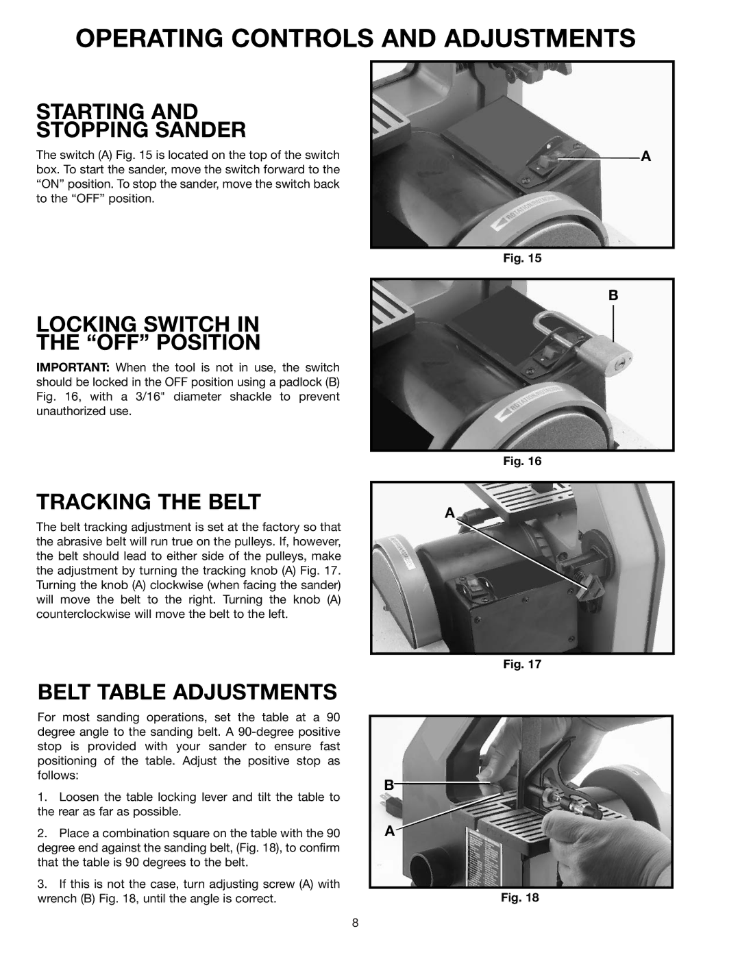
The switch (A) Fig. 15 is located on the top of the switch box. To start the sander, move the switch forward to the “ON” position. To stop the sander, move the switch back to the “OFF” position.
A
Fig. 15
LOCKING SWITCH IN
THE “OFF” POSITION
IMPORTANT: When the tool is not in use, the switch should be locked in the OFF position using a padlock (B) Fig. 16, with a 3/16" diameter shackle to prevent unauthorized use.
B
Fig. 16
TRACKING THE BELT
The belt tracking adjustment is set at the factory so that the abrasive belt will run true on the pulleys. If, however, the belt should lead to either side of the pulleys, make the adjustment by turning the tracking knob (A) Fig. 17. Turning the knob (A) clockwise (when facing the sander) will move the belt to the right. Turning the knob (A) counterclockwise will move the belt to the left.
BELT TABLE ADJUSTMENTS
For most sanding operations, set the table at a 90 degree angle to the sanding belt. A
1.Loosen the table locking lever and tilt the table to the rear as far as possible.
2.Place a combination square on the table with the 90 degree end against the sanding belt, (Fig. 18), to confirm that the table is 90 degrees to the belt.
3.If this is not the case, turn adjusting screw (A) with wrench (B) Fig. 18, until the angle is correct.
A
Fig. 17
B![]()
A
Fig. 18
8