Mode | Alarm Type |
| Alarm Output Operation | |||||||||||
2 | Alarm output will be enabled when the temperature reaches the upper limit. |
| ON |
|
|
|
|
| ||||||
|
|
|
|
|
| |||||||||
| OFF |
|
|
|
|
|
|
|
|
| ||||
y Alarm will be enabled when the PV exceeds SV + |
|
|
|
|
| SV | ||||||||
|
|
|
|
|
|
|
|
| ||||||
|
|
|
|
|
|
|
|
|
| |||||
3 | Alarm output will be enabled when the temperature reaches the lower limit. |
| ON |
|
|
|
|
|
|
|
| |||
|
|
|
|
|
|
| ||||||||
| OFF |
|
|
|
|
|
|
|
|
| ||||
y Alarm will be enabled when the PV falls below SV – |
|
| SV |
|
|
| ||||||||
|
|
|
|
|
|
|
|
| ||||||
|
|
|
|
|
|
|
|
|
| |||||
4 | y Alarm will be enabled when the PV is between SV + |
| ON |
|
|
|
|
|
| |||||
|
|
|
|
|
|
| ||||||||
| OFF |
|
|
|
|
|
|
|
| |||||
|
|
|
| SV | ||||||||||
|
|
|
|
|
|
| ||||||||
| Alarm output will be enabled when the temperature reaches the absolute |
| ON |
|
|
|
|
|
|
| ||||
|
|
|
|
|
|
|
| |||||||
5 | value of the upper and lower limits. |
| OFF |
|
|
|
|
|
|
|
| |||
|
|
|
|
|
|
|
| |||||||
| y Alarm will be enabled when the PV exceeds |
|
|
|
|
|
|
| ||||||
| Alarm output will be enabled when the temperature reaches the absolute |
| ON |
|
|
|
|
| ||||||
|
|
|
|
|
|
| ||||||||
6 | value of the upper limit. |
| OFF |
|
|
|
|
|
|
| ||||
|
|
|
|
|
|
|
| |||||||
| y Alarm will be enabled when the PV exceeds |
|
|
|
|
|
|
|
|
|
| |||
| Alarm output will be enabled when the temperature reaches the absolute |
| ON |
|
|
|
|
|
|
| ||||
|
|
|
|
|
|
|
| |||||||
7 | value of the lower limit. |
| OFF |
|
|
|
|
|
|
|
| |||
|
|
|
|
|
|
|
| |||||||
| y Alarm will be enabled when the PV falls below |
|
|
|
|
|
|
|
|
|
| |||
8 | Standby upper/lower limit alarm |
| ON |
|
|
|
|
|
|
| ||||
|
|
|
|
|
|
| ||||||||
y Alarm will be enabled when the PV reaches SV and exceeds SV + |
| OFF |
|
|
|
|
|
|
|
| ||||
|
|
|
|
|
|
|
| |||||||
| falls below SV – |
|
|
|
|
| SV | |||||||
9 | Upper limit standby alarm |
| ON |
|
|
|
|
| ||||||
|
|
|
|
|
| |||||||||
| OFF |
|
|
|
|
|
|
|
|
| ||||
y Alarm will be enabled when the PV reaches SV and exceeds SV + |
|
|
| SV | ||||||||||
|
|
|
|
|
|
|
|
| ||||||
|
|
|
|
|
|
|
|
|
| |||||
10 | Lower limit standby alarm |
| ON |
|
|
|
|
|
|
| ||||
|
|
|
|
|
|
| ||||||||
| OFF |
|
|
|
|
|
|
|
|
| ||||
y Alarm will be enabled when the PV reaches SV and falls below SV – |
|
|
| SV |
|
|
| |||||||
|
|
|
|
|
|
|
|
| ||||||
|
|
|
|
|
|
|
|
|
| |||||
11 | Upper limit hysteresis alarm |
| ON |
|
|
|
|
| ||||||
|
|
|
|
|
| |||||||||
y Alarm will be enabled when the PV exceeds SV + |
| OFF |
|
|
|
|
|
|
| |||||
|
|
|
|
|
|
|
| |||||||
| the PV falls below SV + |
|
|
|
|
|
|
|
| |||||
12 | Lower limit hysteresis alarm |
| ON |
|
|
|
|
|
|
|
|
|
| |
|
|
|
|
|
|
|
| |||||||
y Alarm will be enabled when the PV falls below SV – |
| OFF |
|
|
|
|
|
|
|
| ||||
|
|
|
|
|
|
|
|
| ||||||
| when the PV exceeds SV – |
|
|
|
|
|
|
|
| |||||
Note:
LED Display
1.When power is normal, POWER LED will be on.
2.After DTC1000/2000 is switched on, all LED will be on. The communication protocol will be displayed in 1 second, followed by the communication address in the next second.
3.RUN LED is on when the control is executing.
4.ERROR LED is on when errors occur in input, memory or communication.
5.When an output is executing, its corresponding output LED will be on.
6.AT LED flashes when PID parameters are being
7.RX LED flashes when DTC1000/2000 receives communication signals. TX LED flashes when DTC1000/2000 sends out communication signals.
Communication protocol displayed on LED after the power of DTC1000/2000 is switched on:
AT |
| TX |
| RX |
| O1 | O2 |
| Err |
| Run |
000: 2,400bps | 001: 4,800bps | 010: 9,600bps |
| Parity 00: None | 01: Even |
| 0: ASCII |
| 0:2 Stop bits | ||
011: 19,200bps 100: 38,400bps |
|
|
| 10: Odd |
|
| 1: RTU |
| 1:1 Stop bit | ||
|
|
|
|
|
|
|
|
|
|
|
|
Communication address display: AT (bit 6) and Run (bit 0) are combined to binary code.
Password Function
The default setting of the password is disabled. To enable the password function, enter the
1.Level 1: Only LED status, SV and PV can be read. No settings can be modified.
2.Level 2: Only LED status, SV and PV can be read. Only SV can be modified.
3.Level 3: All SV can be read. Only SV and
4.Level 4: No password protection.
When a password is set (in 106EH ~ 1070H), the protection will enter Level 1. To enter other levels, enter the corresponding password (in 106BH ~ 106DH). After DTC1000/2000 is switched off, the protection will return to Level 1. To unlock the password protection, the user has to remove all the passwords (in 106EH ~ 1070H).
The password protection level can be read in 106EH ~ 1070H:
bit | b0 |
| b1 |
| b2 |
| b3 |
| b4 |
| b5 | b6 |
Status | Level 1 |
| Level 2 |
| Level 3 |
| Level 1 locked |
| Level 2 locked |
| Level 3 locked | Unlocked |
|
|
|
|
|
|
|
|
|
|
|
|
|
bit = 0 refers to no password is set. bit = 1 refers to the password has been set (b0 ~ b2). b3 ~ b6 display the current level status.
Synchronous Communication Protocol & Auto ID Setup
This function allows the user to set the communication protocol of DTC2000 to the same protocol as set in the first DTC1000. The station IDs of DTC1000/2000 are arranged in decreasing order. Follow the steps below.
1.Set the auto communication ID of DTC1000 to “1” (communication address: 1022H).
2.Switch off DTC1000 before connecting it to DTC2000. Switch it on again.
3.Default communication protocol: 9,600bps, 7 bits, Even, 1 stop bit, communication address 01.
4.This function will consume 3 ~ 5 seconds more when you switch on your DTC.
RS-485 Communication
1.Supports transmission speed: 2,400, 4,800, 9,600, 19,200, 38,400bps;
2.Does not support 7, N, 1 / 8, E, 2 / 8, O, 2 communication format;
3.Communication protocol: Modbus ASCII/RTU;
4.Function code: 03H (read Max. 8 words in register), 06H (write 1 word into register), 01H (read Max. 16 bits of data), 05H (write 1 bit into register).
Address |
| Setting |
| Content | Explanation |
|
|
|
|
| Unit: 0.1 degree. Analog input: 1EU. |
|
|
|
|
| The read values below indicate the occurrence of errors: |
|
|
|
|
| 8002H: Temperature not acquired yet |
1000H |
|
|
| Present temperature value (PV) | 8003H: Temperature sensor not connected |
|
|
|
|
| 8004H: Incorrect sensor type |
|
|
|
|
| 8006H: Unable to acquire temperature, ADC input error |
|
|
|
|
| 8007H: Unable to read/write the memory |
1001H |
| 0 |
| Set point (SV) | Unit: 0.1 degree. Analog input: 1EU. |
1002H |
| 6,000 |
| The content shall not be bigger than the range. Unit: 0.1° | |
1003H |
|
| The content shall not be smaller than the range. Unit: 0.1° | ||
1004H |
| 12 |
| Input sensor type | See the table in “Input” section. |
1005H |
| 0 |
| Control method | 0: PID, 1: ON/OFF, 2: Manual, 3: programmable PID |
1007H |
| 4 |
| Control cycle of Output 1 | 0 ~ 99, 0: 0.5sec |
1008H |
| 4 |
| Control cycle of Output 2 | 0 ~ 99, 0: 0.5sec (Invalid when the 2 outputs are the same |
|
| control.) | |||
|
|
|
|
| |
1009H |
| 476 |
| Proportional band value | 1 ~ 9,999, Unit: 0.1°. Analog input: 1EU |
100AH |
| 260 |
| Ti value | 0 ~ 9,999 |
100BH |
| 41 |
| Td value | 0 ~ 9,999 |
100CH |
| 0 |
| Default integration value | 0 ~ 1,000, Unit: 0.1% |
100DH |
| 0 |
| Offset compensation value for proportional | 0 ~ 1,000, Unit: 0.1% |
|
| control (when Ti=0)) | |||
|
|
|
|
| |
100EH |
| 100 |
| COEF setting when in dual control output | 1 ~ 9,999, Unit: 0.01 |
100FH |
| 0 |
| Deadband setting when in dual control | |
|
| output | |||
|
|
|
|
| |
1010H |
| 0 |
| Hysteresis of Output 1 | 0 ~ 9,999, Unit: 0.1° or 1EU |
1011H |
| 0 |
| Hysteresis of Output 2 | 0 ~ 9,999, Unit: 0.1° or 1EU |
1012H |
| 0 |
| Read/write output percentage of Output 1 | Unit: 0.1%. “Write” is only applicable in manual mode. |
1013H |
| 0 |
| Read/write output percentage of Output 2 | Unit: 0.1%. “Write” is only applicable in manual mode. |
1014H |
| 0 |
| 1 scale = 2.8μA = 1.3mV | |
1015H |
| 0 |
| 1 scale = 2.8μA = 1.3mV | |
1016H |
| 0 |
| Temperature offset regulation value | |
1020H |
| 0 |
| Output mode for Alarm 1 | See “Alarm Output” section. |
1021H |
| 0 |
| Output mode for Alarm 2 | See “Alarm Output” section. |
1022H |
| 0 |
| Communication flag | 0: Communication banned, 1: Communication |
1024H |
| 40 |
| Upper limit for Alarm 1 | See “Alarm Output” section. |
1025H |
| 40 |
| Lower limit for Alarm 1 | See “Alarm Output” section. |
1026H |
| 40 |
| Upper limit for Alarm 2 | See “Alarm Output” section. |
1027H |
| 40 |
| Lower limit for Alarm 2 | See “Alarm Output” section. |
102AH |
|
|
| Read/write status | b1: ALM2, b2: °C, b3: °F, b4: ALM1, b5: O2, b6:O1, b7: AT |
102CH |
| 0 |
| Positive/negative proportional output | 0: positive, 1: negative |
102EH |
|
|
| LED status | b0: RUN, b1: ERR, b2: O2, b3: O1, b4: RX, b5:TX b6: AT |
102FH |
|
|
| Software version | V1.00 is indicated as 0x100 |
1030H |
| 0 |
| No. of start pattern | 0 ~ 7 |
1032H |
|
|
| Remaining time of the executed step | Unit: second |
1033H |
|
|
| Remaining time of the executed step | Unit: minute |
1034H |
|
|
| No. of currently executed step | 0 ~ 7 |
1035H |
|
|
| No. of currently executed pattern | 0 ~ 7 |
1037H |
| 1,000 |
| Upper limit of proportional output | 0 ~ 100% upper limit of analog output, Unit: 0.1% |
1038H |
| 0 |
| Lower limit of proportional output | 0 ~ 100% lower limit of analog output, Unit: 0.1% |
1040H~ |
| 7 |
| Number of steps in a pattern | 0 ~ 7 = N refers to the pattern will be executed from Step 0 |
1043H |
|
| to Step N. | ||
|
|
|
| ||
1050H~ |
| 0 |
| Additional number of cycles for a pattern | 0 ~ 199 refers to the pattern will be executed for 1 ~ 200 |
1053H |
|
| times. | ||
|
|
|
| ||
1060H~ |
| 0 |
| No. of the link pattern for the current | 0 ~ 8, 8 refers to end of the program. 0 ~ 7 refers to the |
1063H |
|
| pattern | next pattern No. following the current pattern. | |
|
|
| |||
1068H |
| 1 |
| Run/Stop setting | 0: Stop, 1: Run, 2: Program end, 3: Program hold |
1069H |
| 0 |
| Control selection of Output 1 | 0: Heating, 1: Cooling, 2: Alarm, 3: Proportional output |
106AH |
| 0 |
| Control selection of Output 2 | 0: Heating, 1: Cooling, 2: Alarm |
106BH |
| 0 |
| Unlock Level 1 password protection. | Shall be the same as Level 1 password (106E) |
|
| Read/write allowed | |||
|
|
|
|
| |
106CH |
| 0 |
| Unlock Level 2 password protection. Use | Shall be the same as Level 2 password (106F) |
|
| Level 3. | |||
|
|
|
|
| |
106DH |
| 0 |
| Unlock Level 3 password protection. Use | Shall be the same as Level 3 password (1070) |
|
| Level 2 | |||
|
|
|
|
| |
106EH |
| 0 |
| Unlock Level 1 password protection/Set up | Unlock password before setting it up. |
|
| password | |||
|
|
|
|
| |
106FH |
| 0 |
| Unlock Level 2 password protection/Set up | Unlock password before setting it up. |
|
| password | |||
|
|
|
|
| |
1070H |
| 0 |
| Unlock Level 3 password protection/Set up | Unlock password before setting it up. |
|
| password | |||
|
|
|
|
| |
1071H |
| 1 |
| Read/write communication address | 1 ~ 247 |
1072H |
| 0 |
| Read/write communication format | 1: RTU, 0: ASCII |
1073H |
| 2 |
| Read/write communication speed | 0 ~ 4: 2,400 ~ 38,400 |
1074H |
| 1 |
| Read/write communication data length | 0: 8 bits, 1: 7 bits |
1075H |
| 1 |
| Read/write parity bit | 0: None, 1: Even, 2: Odd |
1076H |
| 1 |
| Read/write stop bit | 0: 2 stop bits, 1: 1 stop bit |
2000H~ |
| 0 |
| SV temperature for Pattern 0 ~ 7. | Unit: 0.1° |
203FH |
|
| SV for Pattern 0 is set in 2000H ~ 2007H | ||
|
|
|
| ||
2080H~ |
| 0 |
| Execution time for Pattern 0~7. | 0 ~ 900 (1 scale = 1 minute) |
20BFH |
|
| Time for Pattern 0 is set in 2080H ~ 2087H | ||
|
|
|
|
5. | Address and content of the bit register (read bits are stored starting from LSB, and written data is FF00H, set the | ||
| bit as 1. 0000H sets the bits data to “0”). |
| |
| 0811H | Temperature unit display | 0:°F, 1: °C (Default) |
| 0813H | Read/write | 0: End (Default), 1: Start |
| 0814H | Run/Stop setting | 0: Stop, 1: Run (Default) |
| 0815H | Program hold flag | 1: Program hold |
| 0816H | Program stop flag | 1: Program stop |
|
|
|
|
6. | Communication format: Command 01: read bit, 05: write bit, 03: read word, 06: write word. | ||
y ASCII Mode
Read Command |
|
|
| Read Response Message |
|
| Write Command |
|
|
| Write Response Message |
| ||
Start word | ’:’ | ’:’ |
| Start word | ’:’ | ’:’ |
| Start word | ’:’ | ’:’ |
| Start word | ’:’ | ’:’ |
Machine address 1 | ‘0’ | ‘0’ |
| Machine address 1 | ‘0’ | ‘0’ |
| Machine address 1 | ‘0’ | ‘0’ |
| Machine address 1 | ‘0’ | ‘0’ |
|
|
|
|
|
|
|
|
|
|
|
|
|
|
|
Machine address 0 | ‘1’ | ‘1’ |
| Machine address 0 | ‘1’ | ‘1’ |
| Machine address 0 | ‘1’ | ‘1’ |
| Machine address 0 | ‘1’ | ‘1’ |
|
|
|
|
|
|
|
|
|
|
|
|
|
|
|
Command 1 | ‘0’ | ‘0’ |
| Command 1 | ‘0’ | ‘0’ |
| Command 1 | ‘0’ | ‘0’ |
| Command 1 | ‘0’ | ‘0’ |
Command 0 | ‘3’ | ‘1’ |
| Command 0 | ‘3’ | ‘1’ |
| Command 0 | ‘6’ | ‘5’ |
| Command 0 | ‘6’ | ‘5’ |
|
|
|
|
|
|
|
|
|
|
|
|
|
|
|
| ‘1’ | ‘0’ |
| Length of response data | ‘0’ | ‘0’ |
|
| ‘1’ | ‘0’ |
|
| ‘1’ | ‘0’ |
Read staring address of | ‘0’ | ‘8’ |
| (byte) | ‘4’ | ‘2’ |
| Write data address | ‘0’ | ‘8’ |
| Write data address | ‘0’ | ‘8’ |
|
|
|
| |||||||||||
data/bit | ‘0’ | ‘1’ |
|
| ‘0’ | ‘1’ |
| ‘0’ | ‘1’ |
| ‘0’ | ‘1’ | ||
|
|
|
|
|
| |||||||||
|
|
|
|
|
|
| ||||||||
|
|
|
|
|
|
|
|
|
|
|
|
|
|
|
| ‘0’ | ‘0’ |
| Data content in | ‘1’ | ‘7’ |
|
| ‘1’ | ‘0’ |
|
| ‘1’ | ‘0’ |
| ‘0’ | ‘0’ |
| 1000H/081xH | ‘F’ | ‘0’ |
|
| ‘0’ | ‘F’ |
|
| ‘0’ | ‘F’ |
|
|
|
|
|
|
| ||||||||
Read length of data/bit | ‘0’ | ‘0’ |
|
| ‘4’ | ‘1’ |
| To write data content | ‘3’ | ‘F’ |
| Write data content | ‘3’ | ‘F’ |
(word/bit) | ‘0’ | ‘0’ |
|
| ‘0’ |
|
| ‘E’ | ‘0’ |
| ‘E’ | ‘0’ | ||
|
|
|
|
|
|
| ||||||||
|
|
|
|
|
|
|
| |||||||
|
|
|
|
|
|
|
|
|
|
|
|
|
|
|
| ‘2’ | ‘9’ |
| Data content in 1001H | ‘0’ |
|
|
| ‘8’ | ‘0’ |
|
| ‘8’ | ‘0’ |
LRC1 check | ‘E’ | ‘D’ |
| ‘0’ |
|
| LRC1 | ‘F’ | ‘E’ |
| LRC1 | ‘F’ | ‘E’ | |
|
|
|
|
| ||||||||||
|
|
|
|
|
|
|
|
|
|
|
|
|
|
|
LRC0 check | ‘A’ | ‘D’ |
|
| ‘0’ |
|
| LRC0 | ‘D’ | ‘3’ |
| LRC0 | ‘D’ | ‘3’ |
|
|
|
|
|
|
|
|
|
|
|
|
|
|
|
End word 1 | CR | CR |
| LRC1 check | ‘0’ | ‘E’ |
| End word 1 | CR | CR |
| End word 1 | CR | CR |
End word 0 | LF | LF |
| LRC0 check | ‘3’ | ‘4’ |
| End word 0 | LF | LF |
| End word 0 | LF | LF |
|
|
|
|
|
|
|
|
|
|
|
|
|
|
|
|
|
|
| End word 1 | CR | CR |
|
|
|
|
|
|
|
|
|
|
|
|
|
|
|
|
|
|
|
|
|
|
|
|
|
|
| End word 0 | LF | LF |
|
|
|
|
|
|
|
|
yLRC Check
LRC check sums up from “machine address” to “data content”, e.g. 01H + 03H + 10H+ 00H + 00H + 02H = 16H. Obtain 2’s complement EA.
y RTU Mode
Read Command |
|
| Read Response Message |
|
| Write Command |
|
| Write Response Message |
| |||||
Machine address | 01H | 01H |
| Machine address | 01H | 01H |
| Machine address | 01H | 01H |
| Machine address | 01H |
| 01H |
Command | 03H | 01H |
| Command | 03H | 01H |
| Command | 06H | 05H |
| Command | 06H |
| 05H |
|
|
|
|
|
|
|
|
|
|
|
|
|
|
|
|
Read start address | 10H | 08H |
| Length of response | 04H | 02H |
| Write data address | 10H | 08H |
| Write data address | 10H |
| 08H |
|
|
|
|
|
|
|
|
|
| ||||||
of data | 00H | 10H |
| data (byte) |
|
|
|
| 01H | 10H |
|
| 01H |
| 10H |
|
|
|
|
|
|
|
|
|
| ||||||
Read length of data | 00H | 00H |
| Data content 1 | 01H | 17H |
| Write data content | 03H | FFH |
| Write data content | 03H |
| FFH |
(bit/word) | 02H | 09H |
| F4H | 01H |
| 20H | 00H |
| 20H |
| 00H | |||
|
|
|
|
|
|
| |||||||||
|
|
|
|
|
|
|
| ||||||||
|
|
|
|
|
|
|
|
|
|
|
|
|
|
|
|
CRC low byte | C0H | BBH |
| Data content 2 | 03H |
|
| CRC low byte | DDH | 8FH |
| CRC low byte | DDH |
| 8FH |
CRC high byte | CBH | A9H |
| 20H |
|
| CRC high byte | E2H | 9FH |
| CRC high byte | E2H |
| 9FH | |
|
|
|
|
|
| ||||||||||
|
|
|
|
|
|
|
|
|
|
|
|
|
|
|
|
|
|
|
| CRC low byte | BBH | 77H |
|
|
|
|
|
|
|
|
|
|
|
|
|
|
|
|
|
|
|
|
|
|
|
|
|
|
|
|
| CRC high byte | 15H | 88H |
|
|
|
|
|
|
|
|
|
yCRC Program Example
unsigned int reg_crc = 0xffff; i = 0; while
{
reg_crc ^= RTUData[i]; |
|
i ++; |
|
for (j = 0; j < 8; j++) |
|
{ |
|
if (reg_crc & 0x01) | reg_crc = (reg_crc >> 1) ^ 0xA001; |
else | reg_crc = reg_crc >> 1; |
} |
|
} |
|
return(reg_crc); |
|
Installation
How to connect maximum 8 DTC1000/2000 controllers by using DIN rail.
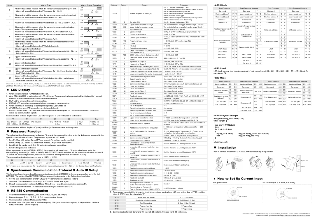
How to Set Up Current Input
For general inputFor current input (4 ~ 20mA, 0 ~ 20mA)
JU MPER
J UMPER
JP1 | PIN HEADER | JP1 |
| ||
|
| PIN HEADER |
DEFAULT SETTING |
|
|
The content of this instruction sheet may be revised without prior notice. Please consult our distributors or download the most updated version at http://www.delta.com.tw/industrialautomation